Atwater Kent Model 206 (2nd Type) Restoration
|
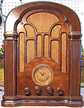
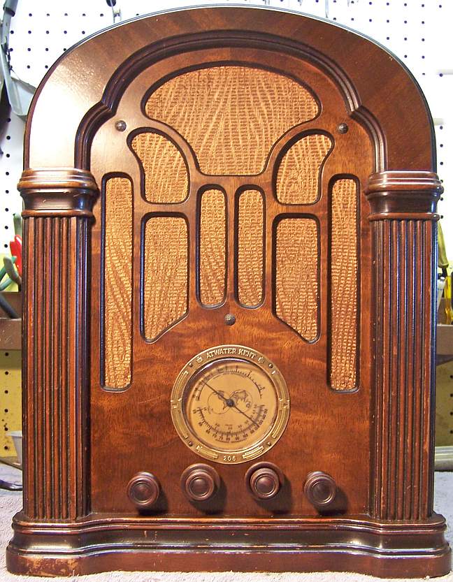
The Atwater Kent Model 206 (2nd type) from about 1934 is a
6-tube AC Superhet with a tuned RF amplifier stage. It receives the
Broadcast, Police, and Short Wave bands. The schematic for the
model 206 (2nd type) can be found on-line at the Atwaterkent.info
web site in the Service
Manual. The schematic is NOT in the Riders Manuals nor is it online at
Nostalgiaair.org (these sources
only have the 1st type schematic).
The radio had seen minimal servicing in the past - all of the original parts
(except tubes) were still in place. I decided to try to maintain the
set in its original condition to the extent possible, yet get it working. However this vintage of AK receivers is difficult to
restore and maintain originality due to the unique cast end resistors and
deteriorating rubber covered wiring used. |
My
antique radio restoration logs
Condition As Found
This radio was purchased on eBay. The cabinet finish,
knobs, and grille cloth were original and in excellent condition. It was
stated in the auction that the radio would power up, but reception could not be
confirmed by the seller. There were no signs of any restoration seen in
the auction listing (although there were minimal photos). I always avoid knowingly purchasing a radio
that has been restored by a collector, as many collectors take shortcuts such as removing
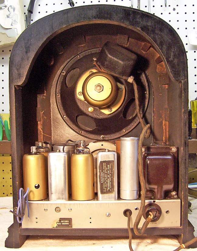
the original capacitors and filters. In this case, the original filter
capacitors and all tube shields were still in place. The only evidence of
repair was a taped splice on the power cord. The chassis was very dirty, but
not rusty.
Previous Repairs
-
All but two tubes were branded RCA/Cunningham and were
engraved base types, and thus were likely the originals. The 80 and
one 58 had been replaced.
-
The power cord was original, but had been spliced and
taped. The power plug looked original (black bakelite or hard rubber)
but had some chips on the edges.
-
There was a piece of spaghetti tubing insulating the antenna
lead on one place where it was likely rubbing the chassis and shorting out.
Survey
My usual restoration procedure is to first make a complete
survey of the condition of all components. The survey results guide my
restoration strategy. I never apply power to a radio before
restoration, even through a "dim bulb tester" or variac "to see
if it works". If major and unique components are defective or
missing and
cannot be restored or replaced, I may elect to sell the radio for parts rather than restore it.
I always assume that all paper and electrolytic capacitors are leaky and thus should be
replaced (I always "restuff" the original containers if possible).
Any mica capacitors are assumed OK until testing proves otherwise.
-
The AC power switch was bad (it measured a high resistance) - dirty and/or oxidized contacts
were likely. It responded to a shot of Big Bath cleaner followed by
repeated cycling and then
worked correctly.
-
The speaker field was OK.
-
The speaker cone was perfect.
-
The output transformer was OK.
-
The power transformer checked out OK. My test procedure is to first
remove all tubes and apply about 10 volts through a fused variac and analog
wattmeter. I then check if the high voltage winding is balanced across
the center tap. An unbalance of more than about 1 volt indicates
possible shorted turns. I then raise the voltage gradually up to the
specified line voltage (110 volts) while monitoring the wattmeter. At
full voltage I check the voltage of all windings, and again check the high
voltage balance. Unloaded, a good transformer will draw less than 10
watts and each half of the high voltage should be equal within a few volts.
-
All RF coils and the IF transformers were OK.
-
All the tubes tested except the 2A6 tested good. The 2A6 tested weak
(470/750)-diodes OK. The 2A7 tube cap had come off and was found
inside the grid cap.
-
Some of the wiring in the radio was rubber covered and the insulation was falling
off. All of this damaged wiring would have to be replaced.
-
Most of the tin foil on the 2A6 cardboard tube shield was missing.
-
The plastic dial cover was missing
-
11 cast end fixed resistors were out of tolerance by more than 20%.
-
The tuning dial drive rubber was functional, but did slip somewhat.
Replacements are available from Adams Manufacturing.
-
Both dial lamps were burned out. These are 2.5 volt screw based (#41)
frosted type - not readily available.
-
The original power cord had been spliced, and the AC plug was chipped (not
sure if it was original). Both could likely be retained.
Repairs
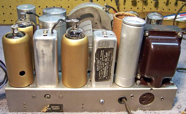
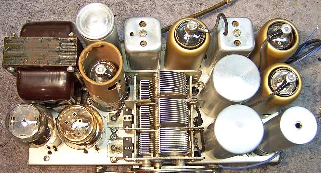
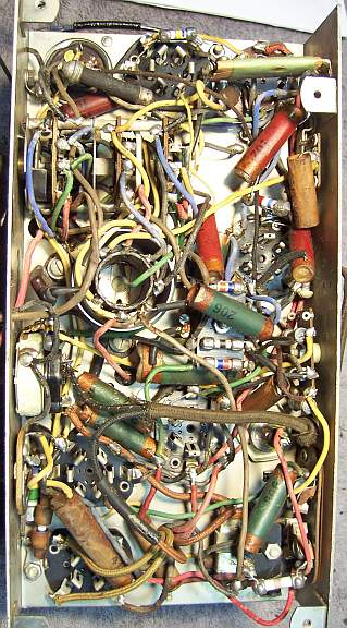
Before starting repairs I made BEFORE photos of the chassis top and bottom. I use these photos to ensure that replacement parts and
wiring are placed as close as possible to their original positions. Some
radios are subject to problems (such as oscillation) if wiring is re-routed or
lead dress is not the same as the original. The Service
Manual for
this radio fortunately had parts placement diagrams. And unlike original
AK documentation, parts values had been written in on the schematic. The
original documentation only contained AK part numbers - no values.
AK resistor color codes are unique and very non-standard. Servicing this radio is very difficult.
Most resistors are cast end dogbone type mounted on terminal strips in groups of
3 or 4. All the wiring in the area of the complex band switch is rubber
covered, and the insulation will fall off if disturbed! One must ensure
that this wiring is not disturbed during restoration, else a lot of work would be
required repair the damage.
All tubes and tube shields were removed. The tuning capacitor and dial
assembly was removed for cleaning and restoration of the tuner support grommets
and dial drive rubber.
The top and sides of the chassis was cleaned with GoJo hand cleaner and 00 steel
wool. Since this process may leave small steel wool fragments that can cause
problems later, I follow up with a thorough vacuuming and go over everything
with a small magnet and masking tape to pick up any stray fragments. I
continue to use steel wool as I have yet to find a substitute that does as good
a job removing the "gunk".
The tuning capacitor was cleaned in my old Heathkit ultrasonic clean (using
dilute
ammonia) followed by thorough rinsing and then cleaning with soap,
water, and toothbrushes. It was then dried using a heat gun. The
drive rubber on the tuning shaft was replaced using a part available from Adams
Manufacturing. The tuning capacitor grommets were replaced using
reproduction parts available from Renovated
Radios (part number GLg-Tuner). These grommets are slightly too thick,
so about 3/32" was trimmed from the thick side using a new single edge
razor blade (the center hole and outside diameter of these grommets is correct
for this radio). The trimmed side was installed on the top of the chassis,
with the now thicker side below.
Insulation breaks in the pilot lamp wiring were repaired using shrink tubing. The
power cord was also re-spliced and insulated at the splice using several layers
of shrink tubing. The original AC plug was cleaned up and reinstalled,
even with its chips. All damaged rubber wiring was replaced using cloth
covered wire of the appropriate color. I always use "unrated"
type wire available from RadioSupply.Com
(their 600 volt rated wire is not appropriate for radio restoration). The
antenna lead was especially difficult to replace, since it must attached to an
almost inaccessible lug on the band switch.
Capacitors
The original power supply filter capacitors were removed and restuffed.
The original filter capacitors were an 8mfd at 475 volt wet type capacitor
(C19), and a 3-section dry type capacitor (C18).
The
capacitor cans were chucked in my Unimat lathe and their cases scored about 1"
from the bottom. The cuts were then completed using a hobby razor saw and
the edges cleaned up using an Exacto knife. The original contents were then removed and the capacitor cases
cleaned inside and out. For the input filter C19 (a wet type) the original positive element was
removed, leaving the aluminum stud. The stud was then cut short, a hole
drilled, and a solder lug attached. The positive lead of a 10mfd/450 volt
capacitor was attached to the solder lug. The negative lead of the new capacitor was extended,
insulated, and then routed though a
small hole drilled into the capacitor base and wrapped around the threaded
portion of the capacitor case. This lead thus contacted the chassis when
the capacitor was mounted. The two halves of the case were then
joined together using a plumbing 3/4" PVC pipe coupling wrapped with
masking tape, and epoxied to each case half. The masking tape is needed
since the couplings are slightly too small in diameter. It also should
make it possible to disassemble the capacitor in the future should that be
necessary.
The 3-section filter C18 was rebuilt by drilling small holes next to each
terminal lug, plus one for the common ground lead near the edge of the
can. The original values were 4 and 8mfd at 450 volts and 10mfd at 25
volts. Replacement values used were 4.7 and 10mfd at 450 volts and 10mfd
at 50 volts. Their positive leads were extended using #22 buss wire and
insulated with spaghetti tubing. The bare buss wires were routed through
the drilled holes in the base and soldered to the original capacitor
terminals. The common ground lead was clamped between the capacitor body
and the mounting clamp. The two halves of the case were then
joined together using a plumbing 3/4" PVC pipe coupling as for C19 above.
All the mica and padder capacitors were left in place after testing for
leakage.
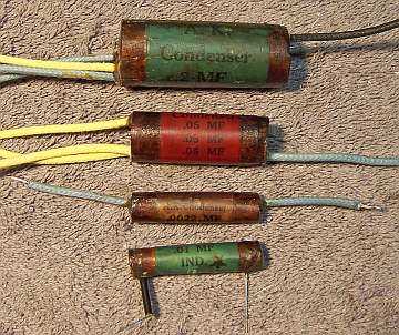
All the original Atwater Kent paper capacitors were rebuilt in their original cases
using modern 630 volt film capacitors in order to maintain the original
under-chassis appearance. Most single capacitors had radial leads,
the bottom capacitor in the photo below (although some had axial insulated
wire leads). My restuffing process is as follows:
- The original capacitor is removed from the radio, and the required lead
length noted.
- The low melting point wax from each end is melted and removed using an old
25 watt soldering iron.
- The "solder" which attaches the radial lead wires to the ends of
the foil roll is then melted and the lead wires freed. This stuff appears to
be some sort of low melting point metal rather than solder. Once the
lead wires are freed from the foil roll, the blob that is left is cut and
the lead wires (which have a spaghetti covering) are carefully
removed by pulling them through the holes in the outer tube.
- Any remaining metal and wax is then removed from each end using heat and
scraping.
- While the wax is still molten, a small screwdriver is pushed through the
center of the foil roll on one end, forcing out a center portion of the
paper-wax roll from the other end.
- The projecting center of the paper-wax roll is then pulled with pliers and
essentially the foil is unrolled from the center out. One must be
careful not to break the foil roll! If that happens, you will have to
dig inside the foil using an Exacto knife until you can again grab the foil
with needle nose pliers.
- Once enough of the original foil is removed to allow room for the
replacement film capacitor, the replacement is wrapped in a narrow strip of
paper towel in order to keep the new capacitor from falling out.
- Radial lead wires are then covered with a piece of small spaghetti tubing
about 1/2" long and are inserted through the original holes in the
capacitor's cover (some original capacitors did not have this spaghetti).
- The lead wires are then attached to the replacement capacitor's leads and
soldered (a small loop is formed in the end of the new lead wire, which is
placed over the lead of the replacement capacitor). Any excess lead
length on the replacement capacitor is then cut off.
- The finished capacitor is then sealed with melted rosin (salvaged from RCA
catacombs, and also donated by members on Antique
Radio Forums).
Below are typical Atwater Kent
capacitors that have been restuffed with modern components. In the AK206,
only one capacitor C14 is a dual unit (the tone control capacitor) - the rest are
all singles.
The line bypass capacitor C20, 0.01mfd at 400 volts, was a problem. The
original was a metal clad unit with terminals on each end. It was mounted
using a clamp. It was leaky and had to be replaced. There was no
room inside the original case to mount a new film capacitor. The case was
opened and the original contents removed. A 0.01mfd/630 volt film
capacitor was mounted below the original where it is hidden. Its leads
were attached to the original's terminals.
Resistors
There were 11 cast-end resistors that needed replacement. Wattage
ranged from 1/3 to 2 watts. Most were 1/3 watt units. Several
strategies were used to replace these resistors in order to retain the original
under chassis appearance.
- R15, a 20K 2 watt unit did not have cast ends, and looked like a normal
dogbone resistor with leads wrapped around the ends. It was replaced
using a 20K 2 watt dogbone (measured 22K) painted black with silver ends,
like the original.
- R17, a 500 ohm 1 watt cast end resistor was replaced using an old style
500 ohm 1 watt carbon composition resistor (fatter and longer than today's 1
watt resistors) which was the same diameter as the original resistor.
The original resistor body was crushed and removed from the end caps.
One end could be pulled out. The other end was removed by crushing the
porcelain and digging out the pieces using a variety of tools. Small
holes were drilled in the center of each end cap. The inside of each
cap was enlarged slightly using a sharp Exacto knife with a #11 blade.
The leads of the resistor were passed through the drilled holes, and the
resistor body attached to the end caps using Epoxy cement. The
original resistor's radial leads were clipped off flush to the end caps, and
the resistor leads used to mount the resistor. The resistor body was
painted flat white, and then the appropriate stripes added using Hobby
enamel paint.
- In a few cases, I had salvaged cast end dogbone resistors that were within
tolerance. I collect used dogbone and AK cast end resistors, and
never throw one away!
- In several other cases, I had salvaged cast end dogbone resistors that had
drifted to within tolerance. These were repainted with the correct AK
color code using Hobby paint.
- In one case, I attempted to cast a reproduction using a mold fabricated
from Putty Epoxy. This did not turn out very well, so this was
abandoned (one was actually used).
- For several of the smallest 1/3 watt resistors, I used a normal 1/2 watt
carbon resistor for the body. The original resistor body was removed
and holes drilled in the end caps. The body of the replacement
resistor was painted the correct color code using Hobby paint, and its leads
passed through the end caps and attached to the original radial leads.
The resistor was not actually attached to the end caps, but was placed close
as possible. The resulting resistor was slightly shorter than the
original, but looks OK.
Dial Lamps
The dial lamps were originally 2.5 volt screw based FROSTED
bulbs. I could find no sources for replacements. So the alternative
was to use standard clear #41 bulbs (2.5 volts, 0.5 amps, screw based) and find
a way to frost them. I posed this question on Antique
Radio Forums, and got several good suggestions. Suggestions included
using frosted glass paint, candle wax, wood glue, and sanding with emory
paper. I first tried sanding the bulb with emory paper while chucked in my
small Unimat lathe. It seemed to work great! But when I proceeded to
install the bulbs in their sockets, both snapped off near the base! I
suppose the sanding weakened the bulb too much. Next I tried applying two
coats of standard wood glue using a small brush, allowing them to dry between
coats. This seemed to work well enough and provided some needed diffusion.
Cabinet
The cabinet needed a good vacuuming inside and then cleaning on the
outside with GoJo and 00 steel wool. No further treatment was needed.
A new dial cover was fabricated using a kit sold by Bill Turner on Dialcover.com.
Bill's web site also has the instructions for making a replacement dial cover.
Testing and Alignment
Once the radio chassis was reassembled and the tubes installed, power was brought up
slowly using a variac. AC power consumption was monitored using a watt meter, and a
DVM monitored the B+. The radio came to life immediately and worked
well. The radio was then aligned using the instructions in the Service
Manual. The radio is quite sensitive, and also has very good tone due
to the large electrodynamic speaker and solid cabinet. I left the original
(weak) 2A6 tube in place - I doubt if a new tube would make any significant
difference in performance.
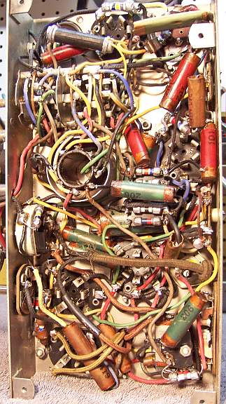
Restoration Results
Chassis Bottom Before and After Restoration