Atwater Kent Model 637 Restoration
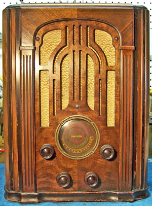 |
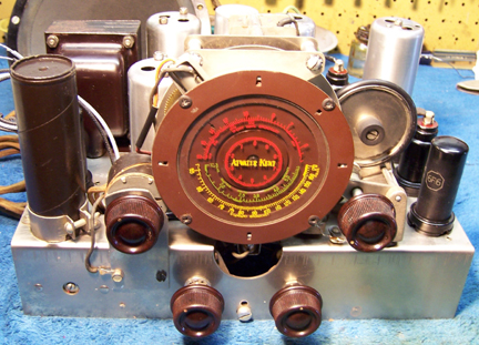
The Atwater Kent model 637 is a 7-tube AC superhet circuit radio.
It receives the standard broadcast band and two short wave bands. The
circuit is conventional, with a tuned RF amplifier stage. It uses all
metal tubes, typical of the mid 1930's. It features a complex
two-speed tuning control in which the speed is selected by moving the tuning
knob up or down. Various parts of the dial are lighted depending on
the band selected. It also has a "split second" dial for
precise tuning.
The radio had seen
minimal servicing in the past and had not been hacked excessively. Previous servicing included several replacement tubes (I assume all the
original tubes originally would have been RCA-Cunningham branded metal tubes), one
audio coupling capacitor and two resistors. This being the case, I
decided to try to retain the original top and bottom chassis appearance if
possible.
The schematic for the AK 637 can be found on Nostalgia
Air. Any part numbers will refer to numbers on that schematic. |
My
antique radio restoration logs
Survey
My usual restoration procedure is to first make a complete
survey of the condition of all components. The survey results guide my
restoration strategy. If major and unique components are defective or
missing and
cannot be restored or replaced, I may elect to sell the radio rather than restore it.
I assume that all paper and electrolytic capacitors are leaky and thus should be
replaced (I always "restuff" the original containers if possible).
Any mica capacitors are assumed OK until testing proves otherwise.
-
The AC power switch was bad - dirty and/or oxidized contacts likely.
-
The AC line cord was original but serviceable. The plug had been replaced.
-
The large rubber rim on the two-speed tuning mechanism was loose (stretched) and had deteriorated
-
The tuning mechanism was jamming.
-
The tone switch contact arm was bent and not making contact
with the switch contacts
-
All the tubes were good, but several were the incorrect
types. A 5Y3GT replaced the 5Z4. A 6F6G replaced the 6F6.
A 6H6G replaced the 6H6. A 6K7GT replaced the 6K7 IF amplifier.
The 6F6G and 6H6G were welcome additions to my tube stock (for Zenith
restorations!)
-
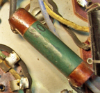
R13 (425 ohm, 1 watt cast end type resistor) was open and
had been replaced by a 400 ohm dogbone type resistor. R16 (30K, likely
originally an AK cast end type) had been replaced by a 27K 1 watt carbon
composition type resistor. R3 (25K) had a lead broken off flush with
the body. R10 (100K) was +25%. The remaining resistors were within tolerance - some VERY
CLOSE to specifications.
-
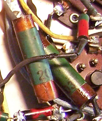
C15 (AK type 203, .01mfd) had been replaced by a 0.02mfd modern type molded capacitor. All other capacitors, including the filter
capacitors, were original.
-
The rubber grommets supporting the tuning capacitor were still good (unusual).
-
All coils and transformers were OK.
-
The speaker field and cone were OK.
-
The cabinet was literally in 5 pieces! The glue had apparently failed completely. The original cabinet finish was in good
condition.
-
All four knobs were incorrect
-
The grille cloth was perfect
Repairs - Resistors and Capacitors
All paper capacitors were rebuilt in their original cases
using modern 630 volt film capacitors in order to maintain the original
under-chassis appearance. AK capacitors are very difficult to restuff,
since the outer shell is not the usual rigid cardboard tube. It is only
several layers of thin paper and easily damaged. My restuffing process is
as follows:
- The original capacitor is removed from the radio, and the required lead
length noted.
- The low melting point wax from each end is melted and removed using an old 25 watt
soldering iron.
- The "solder" which attaches the radial lead wires to
the ends of the foil roll is then melted and the lead wires freed. This stuff appears to be some sort of low
melting point metal rather than solder. Once the lead wires are freed
from the foil roll, the blob that is left is cut and the lead wires (which have a
spaghetti covering) are carefully removed by pulling them through the
holes in the outer tube.
- Any remaining metal and wax is then removed from each end using heat and
scraping.
- While the wax is still molten, a small screwdriver is pushed through the
center of the foil roll on one end, forcing out a center portion of the paper-wax roll
from the other end.
- The projecting center of the paper-wax roll is then pulled with pliers and essentially
the
foil is unrolled from the center out. One must be careful not to break the foil
roll! If that happens, you will have to dig inside the foil using an
Exacto knife until you can again grab the foil with needle nose pliers.
- Once enough of the original foil is removed to allow room for the
replacement film capacitor, the replacement is wrapped in a narrow strip of
paper towel in order to keep the new capacitor from falling out.
- Radial lead wires are then covered with a piece of small spaghetti tubing
about 1/2" long and are inserted through the original holes in the
capacitor's cover.
- The lead wires are then attached to the replacement capacitor's leads and
soldered (a small loop is formed in the end of the new lead wire, which is
placed over the lead of the replacement capacitor). Any excess lead length on the replacement capacitor is then
cut off.
- The finished capacitor is then sealed with melted rosin (salvaged from RCA
catacombs, and also donated by members on Antique Radio
Forums).
One original AK capacitor (C15) had been
replaced. In order to keep the under-chassis appearance original (and
having no AK dud capacitors in stock to restuff) I decided to try to reproduce
the missing capacitor. The radio contained another type 203 original
capacitor for reference. I found a dud wax-paper capacitor in my stock of
duds that was the correct size, and with minimal printing on the body. It
was then cleaned out and restuffed using a 0.01mfd 630 volt film
capacitor. An identification label was then printed using MSWord that was close
to the original color and type font. The reproduction capacitor shown
below was later "aged" by dipping the completed capacitor in amber
shellac.
 |
 |
 |
|
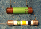
An Original 203 Cap |
Reproduction Cap (and the rebuilt R13 cast end resistor) |
Reproduction Installed (left) - an original below |
The two can type electrolytic capacitors were also rebuilt in their original
containers (one was a wet type, the other a triple dry type). The
cardboard cover was removed from C18, the triple dry type capacitor. The
metal cans were scored on a Unimat lathe and the cut completed
using a hobby razor saw. The cuts were near the base in both cases so that
the joint would be hidden by the clamps or insulating cover. The original
contents were removed, the cases cleaned, new 450 volt electrolytics installed
inside, and the two halves of the cans joined using PVC plumbing couplings and
epoxy. In both cases, the original connecting lugs were used. For
the triple capacitor (C18) small holes were drilled close to the lugs and leads
to the replacement capacitors routed through the holes and soldered to the lugs.
The original R13, a 425 ohm 1 watt cast end type dogbone resistor, was
open. Fortunately it was still in the radio and had been shunted by a 400
ohm dogbone type resistor. This resistor is mounted in a clamp, so its
diameter is critical. I decided to try to rebuild the resistor. The
steps were:
- I first took a photo of the original resistor and measurements of the
diameter and length.
- The ceramic tube was then crushed as close as possible to the cast metal
ends.
- The remnants of the tube were then removed from the cast ends. This
is a difficult process. I used various tools such as nail sets and
ice picks to shatter the ceramic and then pick out small pieces at a time.
- Once the cast metal ends were clean, I center drilled a small hole in each
end to clear the leads of the replacement resistor.
- The original diameter of the ceramic tube was 1/4", so I decided to use an
ordinary piece of 1/4" wooden dowel to replace it. The dowel was
first drilled to accept the replacement resistor(s) on a lathe. The
original resistor was 1 watt, but a 1 watt carbon resistor was too large to
use (about the same size as the wooden dowel). So I used two 1/2 watt resistors in series: a 200 ohm and a 240
ohm. The combination in series measured 425 ohms - the exact value
needed - and both together would be rated at about 1 watt.
- The two resistors in series were placed inside the wooden dowel, with their leads
protruding through the holes drilled in the cast metal ends. The
wooden dowel was then attached to the metal ends using epoxy.
- The wooden dowel was then painted to match the original ceramic tube using hobby paint.
The result is shown in the photo above.
The non-original replacement for R16 was removed. For a replacement I used a
resistor
that was similar to the other resistors in the set. The same was true for R3 and
R10. The replacements were from Philco radios of the same time period
(they are similar in appearance to AK resistors).
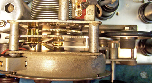
Tuning Mechanism
As received, the tuning mechanism would jam after a very small rotation of the tuning
knob. Upon careful examination, it was determined that the jam occurred
with each revolution of the "split second" dial. The mechanism was disassembled. It was determined that the drive gear for the
"split second" dial had split, thus leaving a large gap between the
teeth at one point. Since finding a replacement for this gear and shaft would be
impossible, I decided to try some creative repair. The teeth on the
leading and trailing side of the split were filed so that the drive gear would mate
smoothly with the driven gear. After some experimentation and filing, the
two gears would work together (there remained a minor "bump" with each
rotation of the "split second" gear).
The large rubber tire on the slow speed idler pulley was loose. The
two smaller rubber drive parts were OK and functional. I decided to
purchase a replacement kit from Adams Manufacturing for this radio. This
kit contains the large rubber O-ring of the proper size to replace the tire, and
also contains the other two rubber parts, which were not used. If one has
access to a large traditional hardware store with a good selection of O-rings
and plumbing parts,
the required part could be found. Since I am out in the middle of nowhere,
I decided to go the easy route vs. driving 100 miles or so looking for the
required part. Here is the cleaned and operational tuning mechanism:
Volume Control
The original AC switch on the volume control was bad. The leads to the
volume control potentiometer were the usual rubber covered wiring that was falling apart if
moved or touched. Also there was a cardboard cover on the control that was coming
apart (apparently it covered the AC switch terminals which would otherwise have
been exposed, since the control is on a bracket above the chassis). The
cover was removed, and the control disassembled. The switch was flooded
with Big Bath cleaner and operated manually until the switch worked. The cardboard
cover was re-glued.
Other Repairs
- The chassis was cleaned using GoJo and steel wool, tooth brushes, small
bottle brushes, and pipe cleaners.
- The cabinet parts were re-glued and clamped. There was a definite order
for reattaching the parts, and all surfaces must be glued at one time - not a
lot of open time!
- The band switch was cleaned using Big Bath spray cleaner.
- The tone switch was removed and disassembled. The bent contact was
restored and the parts cleaned and reassembled.
- Suitable metal tubes (preferably RCA or Cunningham branded) were tested and
installed. This restored the set to all metal tubes, as likely
originally shipped.
- I had the required 4 missing knobs in my stock. Three were the
original push-on types, and one was a set screw type (but all looked the same
from the front of the radio).
Testing and Alignment
Once the radio was reassembled and tubes installed, power was brought up
slowly using a variac. AC power consumption was monitored using a watt meter, and a
DVM monitored the B+. The radio came alive immediately and worked with 110
volts AC input.
Once at full power, voltage measurements were taken.
The set was then aligned - no surprises. One of the IF trimmers was way off
- the rest were close. The oscillator, RF, and low-frequency padder peaked
up nicely. The radio proved to be quite sensitive on all bands. The
tone was also quite good because of the large solid cabinets and 8" dynamic
speaker.
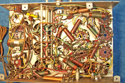
Restoration Results
|
Chassis Before Restoration |
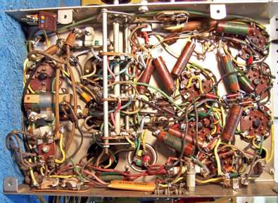
Chassis After Restoration |
 |
 |
|
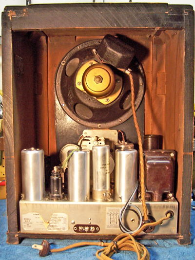
Rear of Radio |
Chassis Front |
 |
 |