Crosley 124-M Play-Time Restoration
|
The Crosley 124-M "Play-Time" is an 8-tube superhet circuit
radio in a grandfather clock cabinet with an electric clock. As purchased, the radio and clock
were said to work. It receives only the broadcast band.
The radio had seen extensive servicing in the distant past, but no
recent restoration judging from the age of the parts used. I decided to
attempt to reverse
all previous repairs to the extent possible and restore the original above and below chassis appearance. The schematic for this radio can be found on-line at Nostalgia
Air. |
My
antique radio restoration logs
Condition As Found
This radio was purchased at the 2012 Charlotte, NC AWA
Conference, in the auction. The cabinet was in
good original condition, as were the
knobs and grille cloth - just the usual wear, dings and scratches. The
finish appeared to be oxidized, and very dark, and especially the pressed wood insert
in front of the radio and speaker. The
radio was sold as working, along with the clock. There was no external evidence that the radio had been
restored. Even the line cord
and plug were original,
and in excellent shape. I always avoid knowingly purchasing a radio that has been
restored, as many collectors take shortcuts such as removing the original capacitors and filters.
I have a another example of this radio in my collection with a
better cabinet that I had previously restored. This radio was purchased because the wife wanted
it to be restored and given to one of our sons (and the price was right at
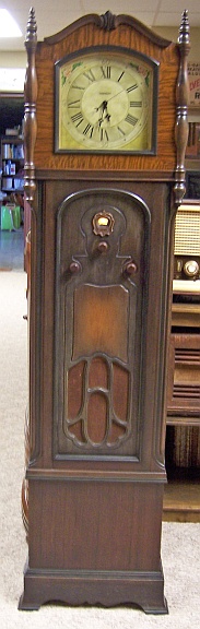
Charlotte!) The last photo in this restoration log shows the original
Charlotte cabinet purchased along with the one in my collection for comparison.
Previous Repairs
-
All tubes had likely been replaced. Only one tube was a
globe type (branded Sylvania), as likely would have been installed originally.
Most of the tubes were branded National Union. I am not sure what
brand of tube Crosley would have used, but most likely they would have been
branded Crosley.
-
Only two original paper capacitors remained. And it
was not 100% certain that these were original, since they did not have
Crosley part numbers. But they were the correct early 1930's vintage
types.
-
Most of
the bypass capacitors in this radio were originally in two metal clad units, one
with two capacitors and the other with four. The dual unit had been
removed completely. The quad unit was still in place, but all its lugs
had been cut off and tubular capacitors installed, mostly just hanging in
space. These replacement capacitors were older units, perhaps circa 1940-1950.
-
The dual filter capacitor had been replaced by two tubular
units under the chassis. The original mounting bracket was still present. This
provided a clue as to the size and shape of the original, which was likely a
rectangular cardboard-cased unit with wire leads.
-
Two original resistors had been replaced. Possibly
others had also been replaced, but the replacements were the same types as
the majority of the resistors (older dogbone types).
Survey
My usual restoration procedure is to first make a complete
survey of the condition of all components. The survey results guide my
restoration strategy. If major and unique components are defective or
missing and
cannot be restored or replaced, I may elect to sell the radio rather than restore it.
I always assume that all paper and electrolytic capacitors are leaky and thus should be
replaced (I always "restuff" the original containers if possible).
Any mica capacitors are assumed OK until testing proves otherwise.
-
The volume and tone controls measured open and were also intermittent and noisy
in operation (when connected to an old analog VTVM, the meter
needle jumped around when the controls were operated).
-
Two chassis bolts was missing (they were hard to find square headed hardware).
-
The speaker field coil was OK.
-
The output transformer was OK.
-
The audio driver transformer was OK. This was fortunate: these
transformers are VERY difficult to
replace and in all other Crosley 124s I have restored this transformer was
open. They are potted in tar also. Since the second detector
tube drives the push-pull 47 tubes directly, the transformer must have a
high inductance primary (and secondary) to avoid distortion. Readily
available Stancor A-53C/A-63C/A-73C transformers or their modern equivalent do
not work well in this application. In a previous restoration of this
same chassis, I used a Stancor A-73C transformer. It worked, but there
was considerable distortion.
-
The detector plate choke was OK.
-
The power transformer was OK. With 20 volts applied to the
primary through a variac, the high voltage was balanced across the center
tap which indicated that there are no shorted turns (a common failure
mode). The the wattage draw at full line voltage was less than 10
watts (real analog watt meter, tubes removed).
-
All tubes were good, although globe types would be correct for this
radio. The only globe type 227 was good, but likely not original
(Sylvania brand).
-
The power cord and plug were original and in excellent condition. The
in-line socket on the clock cord (where the radio plugs in) was present and
in great condition!
-
Two original dogbone resistors were out of tolerance. Two others measured open.
Two original resistors had been replaced: the 47 tube cathode bias resistor
and the 750 ohm B+ screen dropper resistor.
-
Almost all wiring in the radio was cloth covered and was OK.
-
The clock was stated as working. When started it did run, but was
difficult to start. I suspected that it simply needed cleaning and
lubrication.
-
All RF coils and transformers were OK.
-
The second IF transformer had an open secondary. The first IF
transformer was OK. I doubt that this radio would have worked as
stated, at least not very well! This was a potential showstopper!
-
The pilot lamp was bad (although it had continuity).
-
The often-missing tube shield assembly and bottom cover was present (these
are often not replaced during servicing).
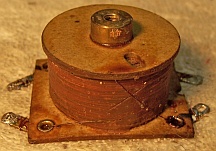
Second IF Transformer
Before starting any repairs and had to deal with a potential showstopper: the
second IF transformer had a open secondary winding. This transformer was
quite unique. No trimmers capacitors were used on either the primary or
secondary winding. The transformer was removed from the radio for
inspection. Here is what is looked like:
I checked where the windings connected to the terminals and scraped and
re-soldered the wires - no change. It appears to be some sort of untuned
transformer. The IF for the radio is 175 KC. I do not know if this transformer
is self-resonant at that frequency, or is simply an untuned transformer. In any
case, it would be very difficult to find a replacement. Even if another
Crosley 124 parts chassis could be found, it was discovered by reading on Antique
Radio Forums that some model 124 radios used a different transformer that
DID have trimmers.
With nothing to lose, I thought I would try the same method that I use to repair
open speaker fields: start unwinding the wire until a break is found, fix the
break, and rewind the wire. It first appeared that the GOOD winding was on the outside, naturally. So
I started unwinding it onto a plastic spool mounted in my small Unimat lathe
with the belt removed, turned by hand. My plan was to remove the good primary
winding (which I originally thought was on the outside), unwind the secondary
until a break was found, repair the break, then return both windings to the
original form. But there was a problem - the wire would hang
up on something as I unwound it. THE DARN THING WAS BIFILAR WOUND! AND
WITH TWO DIFFERENT TYPES OF WIRE! One winding was normal enamel wire,
and the other was double cotton covered. I suppose extra insulation is needed,
since one winding has B+ on it and the other one is grounded, and the wires are
side by side and wound at the same time.
So I then started unwinding BOTH windings at once onto a spool, planning to
continue until I found a break, repair the break, and then rewind. I did not
have to go very far until a break was found. It was repaired, and the wire
returned to the transformer. Once rewound and tested, I applied rosin salvaged
from servicing RCA Radiola Superhet catacombs to seal the winding (the windings had some
sort of wax coating on them originally).
So it looks like the last showstopper to restoration had been removed. Since
very little wire was disturbed, it will hopefully work OK. I suppose the purpose
of the bifilar winding is to create a very close coupling and broad response
(there are no trimmers used).
Repairs
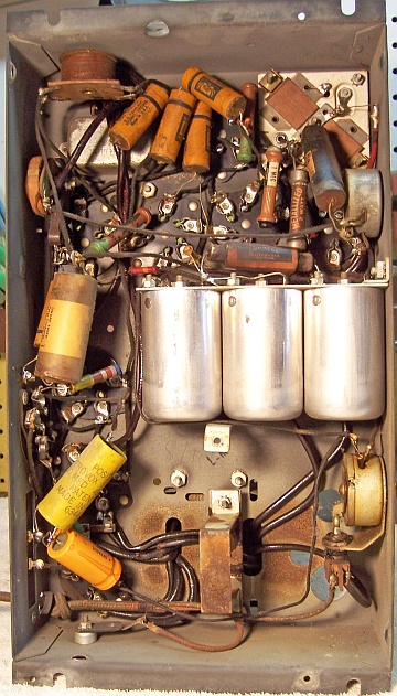
At this point I made BEFORE photos of the chassis bottom. I use these photos to ensure that replacement parts and
wiring are placed as close as possible to their original positions. Some
radios are subject to problems (such as oscillation) if wiring is re-routed or
lead dress is not the same as the original..
All tubes and the tube shield was removed. The tuning capacitor and dial
assembly was removed for cleaning. All non-original parts were then removed and
additional photos taken.
Volume Control and Switch
The volume control on this radio was original. It shunted the antenna coil
primary on one side and the other side varied the bias on the RF and IF
stages. In order to provide smooth control of volume in such non-AVC sets,
the controls often have three different types of resistance wire.
Unfortunately, the control measured open. The usual failure mode is a
defective weld or joint between two different wire sizes.
This control was repaired by inserting a paper thin sliver of brass about 1/8"x3/8" (material
normally
used for model railroad construction) between the two sections of the
resistance wire that had previously been joined. The wiper and resistance
wire were then cleaned using lacquer thinner and a Q-tip. The repair was successful - the control measured
about 4.5K ohms (specifications were 5K) and the resistance
varied smoothly as the control was rotated. This was fortunate, since
there is really no suitable replacement for this type of control. About
the only substitute would be a 5K linear taper potentiometer with switch, or
even better, a control with reverse audio taper. These are VERY difficult
to find. My old IRC Control Catalogue does show a 10K reverse taper control
existed. About the only likely source of one of these would be Mark
Oppat.
The power switch was mounted on the back of the control. It was a conventional
bat-handled switch operated by an arm attached to the rear of the volume control
shaft. The switch was bad - it measured high or infinite resistance,
likely due to dirt and corrosion. It did NOT respond to repeated cleaning
with contact cleaner, and operation. When I attempted to remove the switch
from its mounting bracket, the entire threaded bushing and operating arm
separated from the switch body! It was replaced using a bat-handled switch
from my parts bin. A slot was cut in the handle to allow clearance by the
operating arm. I used a Dremel tool with a cut-off disc, following by smoothing
and shaping using files until operation was smooth. The replacement looked
somewhat like the original, and worked the same way.
Clock
I had restored several of these non-self-starting Hammond clocks
before. Hammond Manufacturing eventually became the Hammond Organ Company
(not to be confused with the Hammond Transformer Company of Canada). The Hammond Organ used similar synchronous motor technology to
spin the organ's tone wheels, which produced the organ tones. My most recent
restoration using a similar clock was in an Erla model 271A. To
start the clock after a power outage, one must
push in on a rear knob and spin counterclockwise, and the speed of
the spin is critical! If power fails, the clock must be restarted and
reset!
At the auction, the clock was stated as working, and it did. Although
starting it was difficult. Once started, it continued to run. I suspected that the
mechanism needed cleaning and lubrication. In some cases the motor capsule
must be rebuilt - a task for an experienced clock repair shop, since the
bushings are likely worn and have to be replaced!
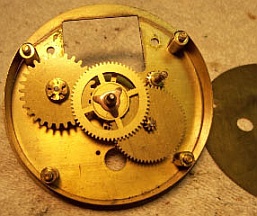
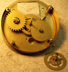
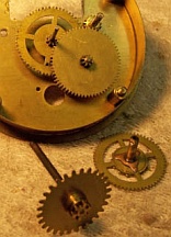
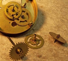
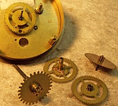
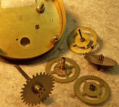
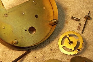
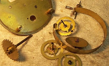
The clock was completely disassembled, and all parts cleaned in lacquer
thinner. To keep track of all the various parts, I took photos as the
mechanism was disassembled, kept the parts in order through the cleaning
process, and made careful notes. Below are the steps of the
movement disassembly.
There did not appear to be any pivot holes with excess wear that would
prevent the gear train from working correctly - lucky! If heavily worn, or
if the pivot holes are oblong in shape or much larger than the pivots, the gears may jam.
The pivot holes can be replaced by a clock repairer, but special equipment is
needed as well as the appropriate replacement bushings that fit the gear pivots
(or can be sized to fit). The
movement was quite dirty and caked with hardened and oxidized grease or oil. The pivot holes in the plates were cleaned with wooden toothpicks and/or
pipe cleaner soaked in lacquer thinner. The movement was then reassembled
and the pivots lubricated with proper synthetic clock oil.
Once assembled, the clock started and continued to run, but appeared to run
slowly (which I assumed impossible for a synchronous motor). Left to run, it did not keep
time and eventually stopped. I attributed this to an assembly error - I
must have installed one of the gears incorrectly. The clock was dismantled
and reassembled using the photos (this time I printed them, vs. viewing them on
the camera!) The clock then started, ran, and kept time when tested
overnight.
I did not mess with the motor capsule - just some lubrication
on the front shaft and bushing.
Resistors
Two original dogbone resistors were out of tolerance by more than 30%, and
two measured open circuit. Two were 1/4 watt size, and two were 1 watt
size. In two cases (1 meg, and 15K, 1 watt) I had a NOS replacement
available that was in tolerance. I collect NOS as well as used dogbone
resistors just for this purpose, and buy all I can find on eBay and at swap
meets. In two other cases, I did not have a replacement available that was
in tolerance. In this case I will find a replacement that is the correct
size and has the correct measured value (within 20% tolerance) but not the
correct markings! I then repaint the resistor with the value required
using hobby enamel paint.
The cathode bias resistor for the 47 output tubes had been replaced by a
newer 5 watt wire wound resistor. The original was a large flexible resistor,
value 220 ohms (one other flexible resistor was used in the radio, which was good). I found a good wire wound flexible resistor in my junk box that
measured 206 ohms and installed that instead. Later, I decided to use the
original resistor (which was good) that was installed in the Crosley I
previously restored. The 750 ohm B+ dropping
resistor had been replaced by an old style tubular carbon resistor. I
assume the original would have been a dogbone type. I replaced it with a
750 ohm 1 watt dogbone resistor that measured 880 ohms. The same resistor
had also been replaced in my first restoration, so I did not have an original
example.
Capacitors
Most of the bypass capacitors in the radio are in two metal cased units with
either 2
or 4 capacitors inside. Having restored about four of these 124
chassis, I have found that there are several variations, and none may match the
published schematic (the values are almost impossible to read anyway)! You
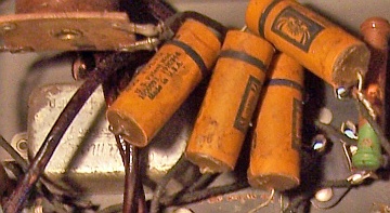
have to restore what you find in the radio. One metal cased capacitor originally held
four 0.1mfd capacitors (another example I restored had three 0.24mfd
capacitors). This capacitor was still in place (riveted to the
chassis and hidden under the second IF transformer), but its lugs had been cut
off and four tubular paper capacitors installed in its place:
The metal capacitor was removed from the chassis and its contents
removed, retaining the original terminal boards and insulation. This
capacitor is installed UNDER the audio interstage transformer, so one must be
careful when drilling out the rivets not to damage the transformer! There
is no way to retrieve the other end of the rivets without partially removing the
transformer. Doing so would likely result in damage to the insulation on
the transformer leads, which are VERY fragile. I simply left the remnants
inside the transformer, which is potted in tar. The capacitor case and insulation
were then soaked in paint thinner and cleaned with old toothbrushes.
One original terminal lug remained. I reconstructed the three clipped off terminal lugs using older type ground
lugs having long lugs. The long ends of the ground lugs were inserted
through the extant slots in the terminal boards. The terminal boards and
ground lugs were then attached to the case using epoxy. Once the epoxy
hardened, new 0.1mfd 630 volt film capacitors were installed. One end of
each replacement capacitor was soldered to each ground lug on the inside, and
the other end soldered to the metal case. The
capacitor was then filled with melted rosin/wax salvaged from servicing 1924 RCA
Superheterodyne catacombs in order to stabilize the contents. This wax melts at a low temperature and will
not damage components.
The other metal cased capacitor, which held two capacitors (0.1 and 0.5mfd),
was missing and had been replaced by two tacked in tubular capacitors.
This capacitor was originally mounted on the inside rear chassis. I did
not have an exact type dud for restuffing. However, I did have a
two-lug metal cased capacitor with the correct mounting centers. But its lugs
protruded from the side rather than the end. I wished to maintain the
original appearance (no visible tacked in components), so this capacitor was
used, even though connecting leads and components to the lugs (which now faced
downward) was difficult. The capacitor was prepared in much the same was
as the other metal capacitor, and restuffed using 0.1 and 0.47mfd 630 volt film
capacitors.
Two (likely) original paper tubular capacitors were still in place. Each of
these was restuffed using 630 volt film capacitors. One of the capacitors
was a Dubilier Cub type, which are difficult to restuff since they have a wooden
dowel down the middle! Here is
my method of restuffing Dubilier Cub capacitors. The other capacitor,
the tone control capacitor (.05mfd, 400 volts, Sprague) was restuffed using this
method.
Filter Capacitor
The original filter capacitor had been removed and replaced by two tubular
electrolytics. But the mounting bracket for the original capacitor was
still in place. This clue indicated the location of the original
capacitor, as well as two of its three dimensions! I searched in vain on
the internet for a photo of a Crosley 124 with the original filter still in
place. There were several different versions of the 124 chassis. I
have seen examples that used normal aluminum screw based electrolytics above
chassis. My chassis had the holes for mounting these capacitors, but the
holes showed no signs of ever being used. The original capacitor held an
8mfd and 6mfd electrolytic. The voltage rating is not documented, but
would have to be at least 400 volts. The original capacitor likely had
wire leads, and was definitely rectangular in shape. It was probably a
cardboard cased unit.
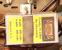
Using the extant mounting bracket for dimensions, I formed a cardboard case using thin
cardboard from the back of a writing tablet. Two 10mfd 450 volt electrolytics were
mounted inside, and wire leads attached and routed through a hole in the
cardboard case. The cardboard case was assembled using carpenters wood
glue and rubber band clamps. The finished case was then painted using aluminum
enamel. A label was fabricated using the correct Crosley part number and
values. The Cornell Dubilier brand and logo was used, since one of the original
capacitors was a CD brand Here is the result (the clamp is original):
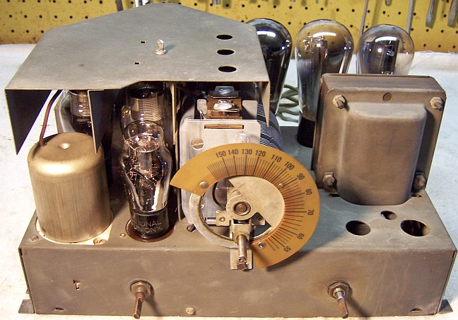
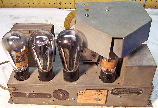
Tubes
A new #41 pilot lamp bulb was fitted. The visible shouldered
tubes (80, and both 47s) were replaced by globe types 280 and 247, since this chassis
would be swapped into my better condition cabinet and become the keeper.
The tube shield hides the other tubes, which were not globe types.
Cabinet
The cabinet only needed a good vacuuming inside and then cleaning on the
outside with GoJo and 00 steel wool. It turned out definitely
presentable, but not as good as my keeper cabinet.
Testing and Alignment
Once the radio chassis was reassembled and the tubes installed, power was brought up
slowly using a variac. AC power consumption was monitored using a watt meter, and a
DVM monitored the B+. The radio powered up and worked immediately. The radio was then
aligned. The radio performs well, is quite sensitive and has very good tone. The
rebuilt volume and tone controls works smoothly.
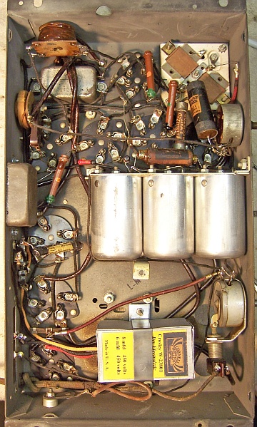
Restoration Results
I was able to successfully reverse all previous repairs and restore the
likely original appearance of the radio under the chassis. Of course, I
did not know the exact appearance of some of the original parts. I have
yet to find photos of an original under-chassis view of the Crosley 124 before
any repairs or restoration. The
replacement filter capacitor was the correct size for two dimensions, but the
third (length) was just a guess.
This chassis and other components of this radio were swapped into my better
condition cabinet, and would become my keeper. The original Charlotte cabinet
and the chassis from my own original 124M would be given away to one of our
sons, or else sold. The Charlotte chassis was more original than my first
Play-Time: the
audio driver transformer and volume controls were original. The cord on
the clock had the attached socket for plugging in the radio. The Charlotte
example had an original Crosley "Tennaboard" antenna installed on the inside of the
cabinet. This was moved to the keeper cabinet. The ST type 47 and 80
tubes from the Charlotte chassis were installed in the give-away/sell
chassis. The clocks were also swapped between units (both were working,
but the keeper had the attached socket for plugging in the radio). While
both radios and clocks worked, my "keeper" chassis sounded much better
and the original volume control operated more smoothly. The original audio
driver transformer in my keeper sounds infinitely better than the other chassis,
which was fitted with a Stancor A-73C transformer. Due to much lower
primary inductance of the A-73C, distortion is noticeable.
Chassis Bottom Before and After Restoration
|
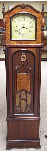
Keeper - My Cabinet
Front |
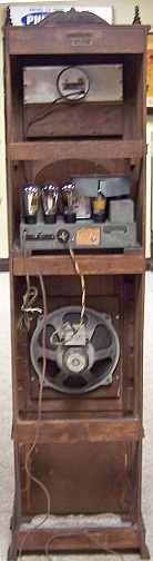
Keeper - My Cabinet
Back |
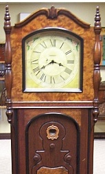
Original Charlotte
Cabinet |
 |
 |
 |