Emerson Model 32 Restoration
 |
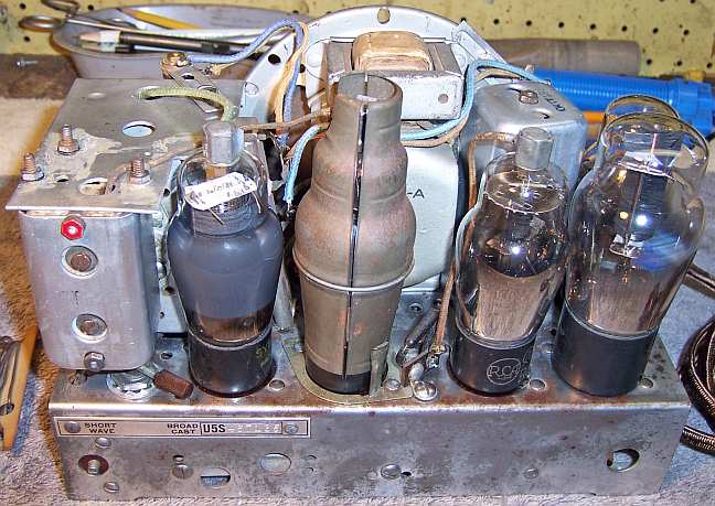
The Emerson Model 32 (chassis U5S) is a five tube AC/DC Superhet that
receives the broadcast band and one short wave band (550-1500kHz and
1.5-3mHz). The radio had been serviced several times in its past, but
many of the original parts were still in place. I decided to try to
reverse all prior servicing and to restore the original chassis appearance
to the extent possible. No recent restoration work had been done
based on the vintage of replacement components used.
The schematic for the Emerson model 32 can be found on-line on Nostalgia
Air.
|
My
antique radio restoration logs
Overview
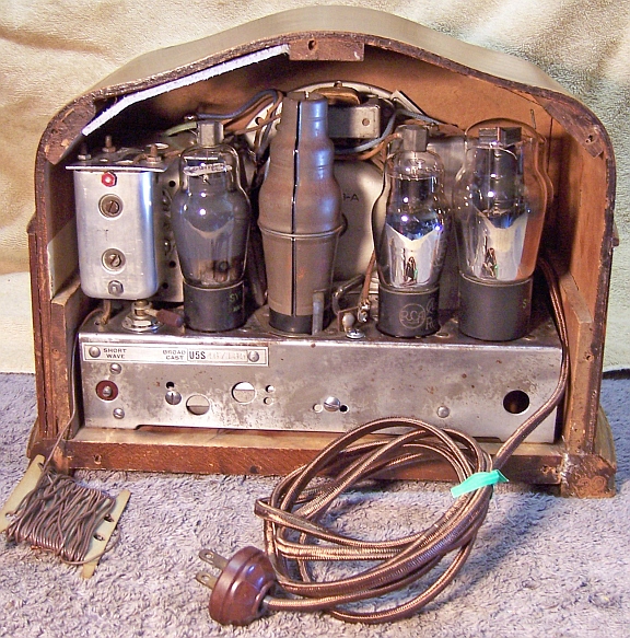
The radio was purchased on eBay and was sold as not working. The
cord had been cut. The radio had been identified by the eBay seller as an
Emerson model 32, and number 32 was stamped on the rear of the cabinet. The
chassis serial
number plate indicated that the chassis number was U5S. But the Riders schematic for the
Emerson 32 did not match my radio! There were some significant differences
found. I manually searched through all of my set of Riders manuals for Emerson
radios having the matching tubes, but did not find a matching schematic. The
circuit used by my radio is quite unusual. It is a 5-tube AC/DC superhet with
AVC using standard base tubes (6A7, 6D6, 75, 43, and 25Z5). But the method of
volume control is quite unusual. In most superhet radios of this vintage,
volume is controlled by varying the audio voltage from the 2nd detector to the
grid of the 1st audio amplifier.
But in my radio, the 1st audio amplifier receives the full audio signal level. The
volume is controlled by a dual taper potentiometer (wiper grounded) which shunts
and antenna coil primary on one end of the control and controls the bias on the IF amplifier
tube on the opposite end.
All examples of radios using this method of volume control that I have seen have
been either non-AVC superhets or TRF sets.
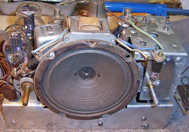
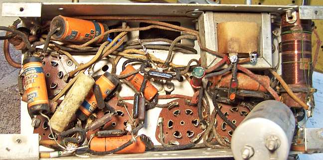
The radio is very compact and difficult to service. Many
components are buried under other parts that must be removed for access. The
radio appears to have been built in layers!
Previous Servicing
I always attempt to avoid purchasing radios that have been
"restored" by radio collectors or flippers, and am looking for either
all original examples or those which have been "lightly serviced" in
the distant past by radio service shops. A service shop would typically replace only enough parts to restore
operation, and no more! This radio had been serviced several times. There was
one service tag on the cabinet bottom dated 1944, when one "condenser"
and the antenna hank had been replaced (Babcock Radio Service - city unknown - 4
digit phone number). Other servicing found::
- Three wax/paper capacitors had been replaced.
- All electrolytic capacitors had been replaced. Two were B+ filters
and two were cathode bypass capacitors.
- All of the tubes likely had been replaced. Three were Sylvania and
two were other brands.
- One resistor had been added from B+ to the cathode of the IF
amplifier. It was a different type than all the rest, and was not seen
in any Emerson schematic.
None of these repairs were recent, based on the vintage of the repair parts
used. The replacement paper capacitors were Sprague "600 Line".
Cleaning
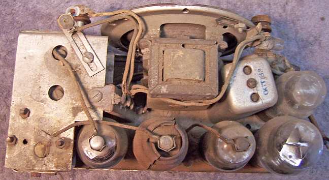
The chassis was very dirty with some rust. All tubes were removed. The dust was blown off, top and bottom, using an air
compressor. Major parts were removed in order to gain access to capacitors
and resistors for replacement, and for cleaning. These included:
The chassis top and sides were then cleaned using GoJo (white)
hand cleaner, 000 steel wool, old tooth brushes and other small brushes.
The steel wool was kept well away from tube sockets and the bottom of the
chassis.
The reduction gearing and anti-backlash mechanism was removed
from the tuning capacitor. The capacitor was cleaned using my old Heathkit
ultrasonic cleaner using dilute ammonia. This required multiple steps,
since the capacitor would not fit in the cleaner's small cleaning tank. Alter
rinsing, the capacitor was further cleaned using soap, water, and old
toothbrushes. Before cleaning, the mica trimmer insulators were removed to
prevent damage. Before removal, each trimmer was tightened and the number of 1/2
turns to fully tight noted. This allowed the trimmers to be returned to their
approximate original positions after cleaning, drying, and reassembly. The
capacitor assembly was lubricated using light turbine oil.
Survey
The first thing I did was to draw a schematic of the radio as
found using several available Emerson schematics for reference. Neither of the
two available Riders schematics using the same tubes matched my radio, but when combined came close. I then assigned
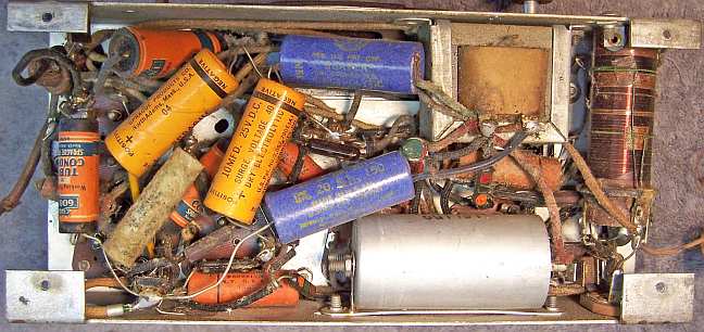
part number callouts to my schematic. Next I took "before" photos of
my chassis, top and bottom. These photos were then annotated using the part
callouts from the hand drawn schematic. I then checked all parts possible before
starting repairs:
-
The speaker field coil was OK (it was the high resistance B+
shunt type).
-
The output transformer was OK.
-
The filter choke was OK.
-
All RF and IF transformers were OK.
-
The volume control was OK. The switch was initially bad, but
responded to a shot of GC Big Bath cleaner through one of the rivet
holes. This is fortunate, since this type of control (combination
antenna shunt and grid bias control) is almost impossible to replace.
-
The metal clad combination filament dropping and pilot lamp shunt
resistor was OK
-
The flexible resistor (43 tube cathode bias resistor) was open.
-
Five small resistors were out of tolerance by more than 20%
(some as high as 50%).
-
Two chassis bolts were missing.
-
One pilot lamp socket center terminal had pulled loose from
the socket.
-
The IF amplifier (6K7G) grid cap lead insulation was worn and
the conductor was shorting
to the transformer shield can.
Restoration Strategy
I assume that all paper capacitors are leaky and thus should be
replaced. I always "restuff" the original components if possible. I do not replace mica capacitors, but may test them in place if
possible (usually this requires disconnecting one lead of the capacitor). Since
many of the original parts were still in place I decided to try to maintain the
original chassis appearance to the extent possible. Normally I would
rebuild all original wax-paper capacitors in their original cases (restuff
them). In cases where an original wax-paper capacitor has been replaced, I
attempt to find an original type capacitor in order to restore the radio to its
original appearance under chassis. I maintain a collection of dud capacitor just
for this situation. In this case, all of the existing original wax-paper capacitors were
Micamold brand. So I assumed that the three capacitors that had been replaced
were also originally Micamold branded. I found quite a few Micamold duds
in my dud capacitor stock with the required values. But I had to guess the
voltage ratings, since the voltage ratings were not on the schematic. Since this was an AC/DC set, I used 400 volt ratings for the
missing 0.1mfd line bypass capacitor and the 0.01mfd audio coupling
capacitor. I used .05/200 volts for the missing 1st audio plate B+
decoupling capacitor.
Repairs
When I replace a component, I always remove the original part
completely from a terminal. Other components connected at the terminal are
protected from heat using old medical clamps (hemostats). I frequently
find and remove wire stubs from previous component replacement. Remaining wire
stubs often provide clues as to the types and connections of components replaced
in servicing. Excess solder is
then removed using a solder sucker in order to expose terminal holes for
reattachment of the rebuilt or replaced component.
Wax/Paper Tubular Capacitors
All original paper/wax capacitors as well as the three Micamold duds used to
replace original parts removed in servicing were restuffed with new 630 volt film
capacitors. Here is my restuffing process:
- The original capacitor is removed from the radio, and the required lead
length and use of insulating sleeving noted. If the original capacitor had
been replaced, then the lead length of the replacement capacitor is used to
specify the lead length.
- Both ends of the Micamold capacitors are crimped, which retains the
paper-foil roll. Each end has a small cardboard disc, and the foil roll is
surrounded by wax. To restuff the tube, one end of the capacitor is sliced off about 1/16"
from the end using a new single edge razor blade. The other end is left as
it was.
- The capacitor is then heated with a heat gun, which allows the foil roll
and leads to be pulled out of the cardboard tube. While still hot, the tube
is wiped clean of dirt and wax using a paper towel, and any remaining wax
inside is also removed.
- The foil roll and wax is discarded, but the two cardboard discs on each
end of the foil roll are kept.
- If the required lead length is longer than that of the replacement
capacitor, a piece of bare buss wire is attached before restuffing. The splice is
hidden inside the tube.
- The replacement capacitor is wrapped in a narrow strip of
paper towel in order to keep the new capacitor centered and to keep it from falling out. One
cardboard disc is fitted to the wrapped replacement capacitor
lead and reinserted into the tube (retained by the crimped tube).
- The finished capacitor is then sealed with melted rosin (salvaged from
early RCA Superhet catacombs, and donated by or purchased from members on Antique
Radio Forums). Before the rosin hardens, the other cardboard disc
is placed over the remaining lead and pressed flush with the end of the tube
- retained by the rosin.
- I do NOT recoat the outside of the rebuilt
capacitors with wax (I'm not sure what was originally used - probably
beeswax).
Filter Capacitors
All of the filter capacitors had been replaced - no original
parts remained. The original filter capacitor block was likely a single
cardboard case unit mounted under the chassis. The schematic lists a
"combination by-pass and filter condenser". There would have been room
for such a capacitor on the bottom front chassis between the filter choke and a terminal strip on the
opposite end of the chassis - both mounted with screws and nuts. The original
filter block had been
replaced by four individual tubular electrolytics. The schematic indicated that
the filter capacitors were 16mfd (input) and 8mfd (output), likely at 150 volts.
Another similar schematic uses two 20mfd filter capacitors.
The 1st and 2nd audio amplifier cathode bypass capacitors were listed as 5mfd. My
restoration strategy was to fabricate a cardboard case capacitor block that
would fit under the chassis between two suspected mounting points. Of course I
had no clue what the original may have looked like. There was a maximum size
known, and the original surely had wire leads, since remnants of these leads
were found on other components and terminals.
I have kept a pattern used to build a replacement rectangular
cardboard box type capacitors. The pattern was constructed by disassembling a
cardboard case capacitor by melting the glue joints, then removing the contents. The various sides and flaps
of this pattern can then be adjusted to the actual size needed and a pattern for
the required capacitor drawn on a piece of thin cardboard from the back of a
writing tablet. The box is then glued up and clamped (rubber bands), leaving one end open. The
replacement parts are then placed inside the box, with wire leads protruding
from a hole punched in one end. I have also built replacement block
capacitors that used terminals vs. wire leads. I used two 22mfd/160 volt
capacitors for the filters, and two 4.7mfd/50 volt capacitors for the bypass
capacitors.
Small Resistors
Five small resistors were out of tolerance by more than 20%
(some as high as 50%). All existing resistors were the small black rectangular
Micamold type. I had a few Micamold resistors in stock, but none were in
tolerance. So I was forced to use 1/2 watt carbon composition resistors to
replace them. The 2nd audio cathode bias resistor originally was a flexible
type resistor, and was open. Again, I did not have a suitable flexible replacement in
stock. But I did have a Micamold type 430 ohm resistor in stock - the original
resistor was listed as 450 ohms. So I decided to use the Micamold
resistor, since it matched the original types used.
Tubes
All of the supplied tubes tested strong. They were all
reused. Three were Sylvania brand, two were other brands. I have no clue
what brand originally would have been supplied.
Pilot Lamp Socket
The center terminal lug of one of the pilot lamp sockets had
pulled loose due to failure of the rivet. The socket was disassembled by
removing the remnants of the rivet, the internal and two external fiber shoulder
washers, and the copper center contact spring. The rivet was replaced using a
4-40 brass screw and nut. The head of the brass screw was ground down flat
and to size so that it could be used to retain the copper inner contact spring.
The socket was then reassembled and the original terminal lug reattached using a
4-40 nut.
Other Repairs
- The line cord was replaced with new cloth covered cord (a modern
reproduction) and old style AC plug.
- The 6A7 grid lead, which was worn and shorting to the metal tuning
capacitor cover, was replaced.
- I found two chassis screws in my junk box that matched the existing screws
exactly.
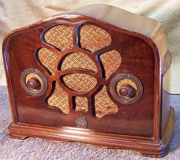
Cabinet
The cabinet was vacuumed then cleaned using GoJo (white) hand cleaner and
paper towels, then waxed. Nothing else was done to it.
Testing and Alignment
After completion of the electronic restoration, power was applied through my
combination fused Variac and isolation transformer. A DVM monitored the B+ voltage. Power
was slowly increased while B+ was monitored. The radio came alive and worked on
both bands. The radio was then aligned. The IF frequency is documented on
the schematic (456kHz). No other alignment instructions were found. The
radio cannot be aligned in its cabinet, since the trimmers cannot be accessed.
The dial scale is attached to the cabinet and thus cannot be used to set the
dial to scale. So I did not change the oscillator trimmer and only peaked
the 1st detector trimmer (on the gang capacitor) at 1400kHz. The short wave
antenna trimmer was peaked at 2.7mHz.
The radio performs quite well on both bands using my basement ceiling mounted
wire antenna, which is about 40' long.
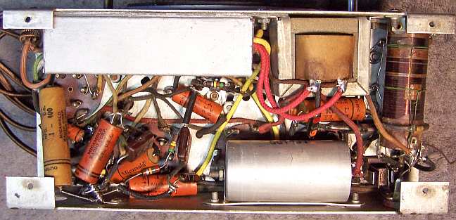
Restoration Results
My original restoration objective was to return the radio to its un-serviced
condition - to reverse any prior servicing - and to restore operation. Ideally no
repairs would be visible. Not all restoration objectives were met, as some of
the original replacement parts were not available or were unknown. Some of
my "misses" were:
- The out of tolerance Micamold resistors were replaced using normal 1/2
watt carbon composition resistors.
- The 2nd audio cathode bias flexible resistor was replaced by a Micamold
fixed resistor (430 ohms and likely wire wound).
- The filter capacitor block was reproduced, but its original appearance and
brand was unknown.
- The line cord was only similar to the original cloth covered wire.
- Some of the wiring had to be replaced.