This example had been serviced at least once in the past, but was almost completely original. I decided to attempt to maintain the original above and below chassis appearance yet get it working.
|
|
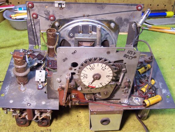
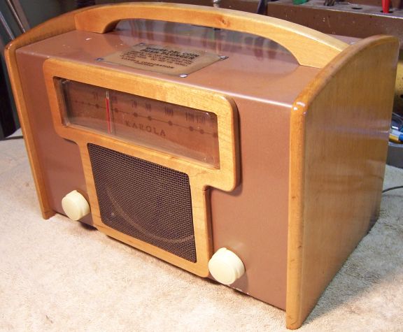
This Karola is a 6-tube AC coin-operated radio typically
used in hotels. The model number is unknown. The chassis is
date stamped January 1947. There are no schematics or other information available for
Karola radios, and very little is known about the brand. No
schematic has been found for any Karola radio.
This example had been serviced at least once in the past, but was almost completely original. I decided to attempt to maintain the original above and below chassis appearance yet get it working. |
My antique radio restoration logs
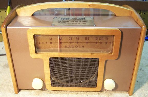
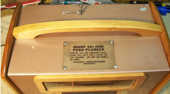
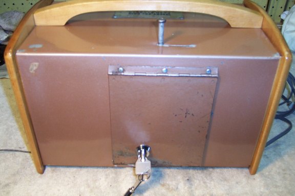
This radio was purchased on eBay. The combination wood and metal cabinet was in good original condition. Most of the clear finish on the wood had flaked off, and there were dings, scratches, and areas of paint loss on the metal cabinet. The radio had been broken into and the access door to the coin box and surrounding area damaged. The lock had been removed (likely a cam lock).
The knobs, line cord, plug, and antenna lead were all original. I always avoid knowingly purchasing a radio that has been restored, as many collectors take shortcuts such as removing the original capacitors and filters. The chassis was dirty as found. According to the eBay seller, this radio was announced in The Billboard Amusement Weekly of June 28, 1947. The chassis (coin mechanism) was date stamped January 1947 also. As usual with Karola radios, no model or serial number was to be found. This radio used all miniature tubes. I have seen this same chassis before using a combination of miniature, loctal, and octal tubes. In fact, three of the holes in the chassis had been punched for loctal or octal sockets, and miniature sockets were factory installed using adapter plates. The radio was sold as "makes noise".
Karola Corporation was located at 922 Washburn Avenue. Minneapolis, Minnesota. 1946 was the first year that Karola Corporation appeared in the Minneapolis city directory. At that time Robert C. Brame was the president. Thus this radio was likely made in 1946 or later. I have seen one other Karola radio which had a red ink stamp on the chassis: "Brame Mfg". So Brame Mfg. may have made products other than Karola radios.
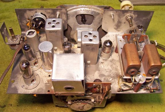
The radio has a standard 6-tube AC-DC superhet circuit using all miniature tubes. But because of the coin mechanism timer motor, it will only operate on AC. It has a tuned RF stage and uses permeability tuning (slug tuned coils) vs. a variable tuning capacitor and fixed inductance coils. An external antenna wire is needed (no loop antenna is used - likely because of the metal cabinet). The tube line up is 12BA6 RF Amp; 12BE6 Converter; 12BA6 IF Amp; 12AT6 2nd detector, AVC, First Audio; 35B5 Audio Output; 35W4 Rectifier.
The radio had been serviced at least once.
All capacitors and resistors, including the filter capacitors, were original.
The line cord and plug were original.
The antenna lead was original and largely intact.
A metal clamp had been installed around a rubber part covering the point where the tuning shaft is joined to the drive shaft for the tuning unit. This was likely installed to prevent the clip joining the two shafts from falling out due to deterioration of the rubber. The clip and rubber cover were likely NOT original. I have no clue what type of connection was originally used. The tuning knob shaft was slotted. The driven shaft (about 1/8" away) was terminated in a round pulley like affair about 3/8" in diameter with some sort of hard black residue on the outside.
Most tubes were branded Tung-Sol and were likely original. It appeared that the 35B5 tube had been replaced by a 50B5 (GE brand). The 50B5 was likely NOT original, since then the filament string would add up to 135 volts vs. 122 volts for a 35B5. It's likely this is what the service man had available at the time!
My usual restoration procedure is to first make a complete survey of the condition of all components. The survey results guide my restoration strategy. If major and unique components are defective or missing and cannot be restored or replaced, I may elect to sell the radio for parts rather than restore it. I never apply power to a radio before restoration, even through a "dim bulb tester" or variac "to see if it works". I always assume that all paper and electrolytic capacitors are leaky and thus should be replaced (I always "restuff" the original containers if possible). Any mica capacitors are assumed OK until testing proves otherwise.
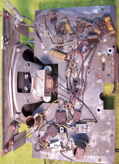
Before starting repairs I made BEFORE photos of the chassis bottom. I use these photos to ensure that replacement parts and wiring are placed as close as possible to their original positions. Some radios are subject to problems such as oscillation or motor boating if wiring is re-routed or lead dress is not the same as the original. Plus one of my restoration objectives is that any repairs should be invisible.
The speaker was replaced by a speaker found in my junk box that turned out to have the correct mounting center hole spacing! Its impedance was likely also correct - it measured 3.2 ohms DC - the same as the original. But it did not have an output transformer attached. The original output transformer was removed from the defective speaker and attached to the replacement.
The original tuning drive mechanism consisted of what looked like a galvanized barbed-wire fence staple which was placed in the slotted tuning shaft and then engaged a rubber part attached to the tuner drive shaft. The rubber part was not firmly attached to the driven shaft, and there was severe backlash in the mechanism due to wear on the rubber part. As found, there was an electrical conduit clamp crimped around the rubber part in an attempt at stabilizing the assembly and to prevent slipping. The clamp and rubber part were removed. The staple as well as the flattened end of the driven shaft were cleaned and tinned. The staple was then placed in the drive shaft slot and soldered to the end of the driven shaft. This prevented excess backlash and shipping. The tuning drive shaft drives the dial pointer through a dial cord and a series of pulleys. The driven shaft turns a rack that moves the cores of the three permeability tuned coils. So the dial pointer and tuner must be set to correspond to what the tuner is selecting before permanently soldering the driven and drive shafts together!
The missing lock was replaced by a 3/8" tubular cam lock with a 1/8" offset cam, purchased from PadLocks4Less http://www.padlocks4less.com/tubular-cam-lock-410.html.
All out of tolerance (more than +/- 20%) resistors were replaced using similar type 1/2 watt carbon composition resistors. The replacements were either 5% or 10% tolerance, vs. the 20% tolerance originals (which are no longer available). 20% tolerance resistors would have been cheaper at the time of manufacture.
All of the original Chicago brand wax/paper capacitors were restuffed using modern 630 volt film capacitors. All mica capacitors were left in place.
The original dual filter capacitor was still in place, rated at 50+50mfd at 150 volts. It was restuffed using two 47mfd 160 volt radial electrolytic capacitors. The original can had corroded from the inside and was very weak. It was damaged during the restuffing process. The mounting tabs had been bent over and one had been soldered to the chassis. After removal, the tabs were in danger of breaking off after straightening them for removal. So another container and mounting tab ring was substituted, keeping the original terminal board. The replacement container was slightly longer than the original and had no value markings.
The original line cord and plug were safe to use and were retained. The original antenna lead was patched using shrink tubing.
All of the original tubes were re-installed except for the 50B5, which was replaced by a 35B5.
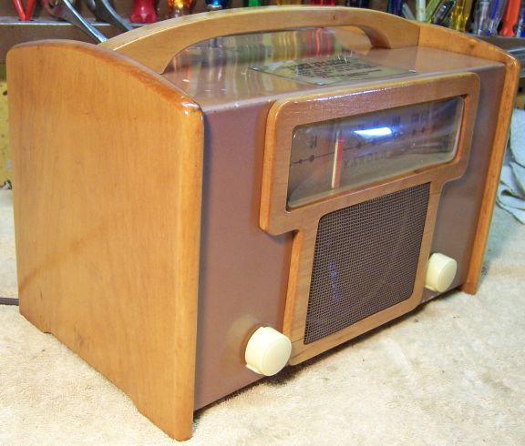
The cabinet needed a good vacuuming inside and then cleaning on the outside with GoJo and 00 steel wool. It turned out presentable without repainting the metal parts. The front grille, made of thin wood, was broken in two places as found. It was removed from the metal cabinet, repaired using carpenter's wood glue, and reinstalled. The remnants of the clear finish on the wooden parts was removed using light sanding and 00 steel wool. After vacuuming and cleaning with lacquer thinner, a couple of light coats of gloss spray lacquer were applied (likely the original finish).
The back had been broken into and the lock removed. The lock was replaced by a standard 5/8" tubular cam lock. The original may have been this type or may have been a tumbler type lock. This type was chosen because of its small depth. The 3/4" diameter housing fit the existing hole exactly. The supplied cam had to be cut down about 1/8" in length in order to clear the back when unlocked. The coin box apparently never had a lock. Instead, there was a rubber grommet which bore against the back cover when secure, thus preventing the coins from falling out.
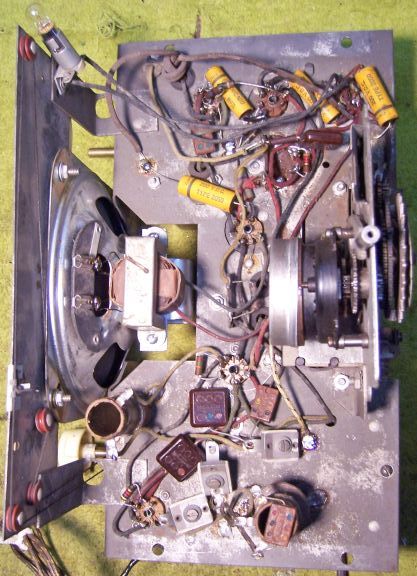
Once the radio chassis was reassembled and the tubes and tube shield installed, power was brought up slowly using a variac and isolation transformer. The radio powered up OK and worked very well. The radio was then aligned, although I did not attempt to adjust the tracking of the permeability tuner. Only the IF transformers and trimmer capacitors were peaked up. The IF frequency was 455kHz. The set is fairly sensitive since it has a tuned RF amplifier stage. The tone is nothing to write home about (the speaker was replaced).
I was able to maintain the original appearance of the radio under the chassis with a few exceptions: the volume control and speaker had to be replaced. The tuner drive mechanism was modified to work reliably with minimum backlash. The missing coin box lock was replaced by a tubular cam lock. The original may have been either a tubular cam lock or keyed cylinder lock. There was no attempt at restoration of the damaged areas of the metal cabinet parts.
 |
 |