Philco Model 19B Cathedral Restoration
|
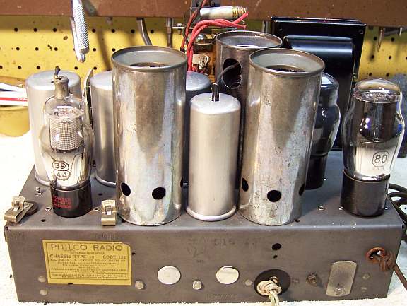
The Philco 19B Cathedral from 1934 is a 6-tube superhet with
an RF amplifier stage. This example was Code 126. The Philco
19 is very
similar to the Philco 89, but has a Shadow Meter tuning aid.
The Philco 19, like the model 89, went through many changes and
revisions during its life. It is difficult to find an accurate schematic
for Code 126. The most accurate I was able to find was on Philco
Radio, where the evolution of the model 19 is discussed. This
information must be supplemented with schematics from Nostalgia
Air under various model 19 variations and also under model 89.
The schematic on Philcoradio.com is difficult to read, at least the part
numbers. I was able to identify and write in the parts and part
numbers using the Code 128 schematic on Nostalgia Air.
The radio had seen minimal servicing in the past -
most of the original parts were still in place. I decided to try to reverse
all previous repairs to the extent
possible. |
My
antique radio restoration logs
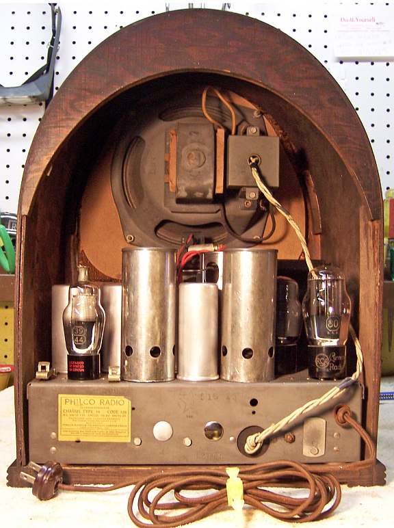
Condition As Found
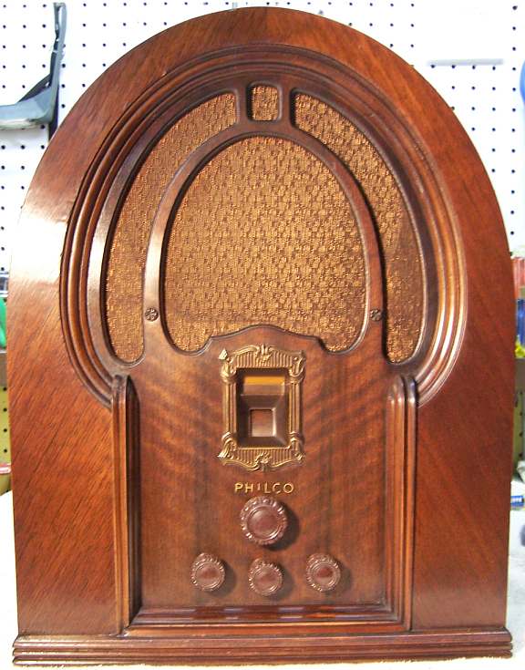
This radio was purchased at the 2011 Charlotte AWA Radio Conference in
the auction. The cabinet was in excellent original condition, as were the
knobs and grille cloth. There was no evidence that the radio had been
restored, although one filter capacitor was missing and there was tape on the
leads to the Shadow Meter. I always avoid knowingly purchasing a radio
that has been restored by a collector, as many take shortcuts such as removing
the original Philco bakelite block capacitors and filters.
Previous Repairs
-
One original filter capacitor had been removed and replaced by a
tubular electrolytic under the chassis
-
A couple of tubes had been replaced - the remainder were
Philco branded and possibly original
-
The leads to the Shadow Meter had been cut, spliced back,
and taped over. The pilot lamp behind the meter had been
removed. This indicated that the meter was likely OPEN - later confirmed.
-
The shield base for the type 36 tube had been removed, and
the tube socket was retained by only one rivet.
-
All the original Philco bakelite block capacitors and
resistors were still in place.
-
It appeared that the dial cord had been replaced by a piece
of heavy cotton cord.
Survey
My usual restoration procedure is to first make a complete
survey of the condition of all components. The survey results guide my
restoration strategy. If major and unique components are defective or
missing and
cannot be restored or replaced, I may elect to sell the radio rather than restore it.
I always assume that all paper and electrolytic capacitors are leaky and thus should be
replaced (I always "restuff" the original containers if possible).
Any mica capacitors are assumed OK until testing proves otherwise.
-
The AC power switch was bad (it measured high resistance) - dirty and/or oxidized contacts
were likely.
-
One tube shield and its shield base was missing (for the type 36 first
detector tube).
-
One chassis bolt was missing.
-
The tuning capacitor grommets were bad - typical of the age.
-
The rubber chassis washers were bad - again typical.
-
The speaker field and cone was OK.
-
The output transformer was OK.
-
The power transformer checked out OK
-
All RF coils and IF transformers were OK.
-
The two 44 tubes as well as the 42 tube were bad. The remaining tubes
were OK.
-
The power cord looked original and in good condition, but needed a new plug.
-
All original dogbone resistors were within tolerance - very unusual!
-
Almost all wiring in the radio was cloth covered and was OK. There
were insulation breaks in the speaker cable and on a couple of grid cap leads.
-
The combination band switch and power switch appeared to have been removed
and reinstalled incorrectly. It was rotated 90 degrees. As
installed, the short wave band would not have worked. My guess is that
a repairman removed it in order to remove the bad filter capacitor, replaced
it, and never checked the short wave band.
-
The shadow tuning meter was open, and its shunt resistor showed signs of
overheating.
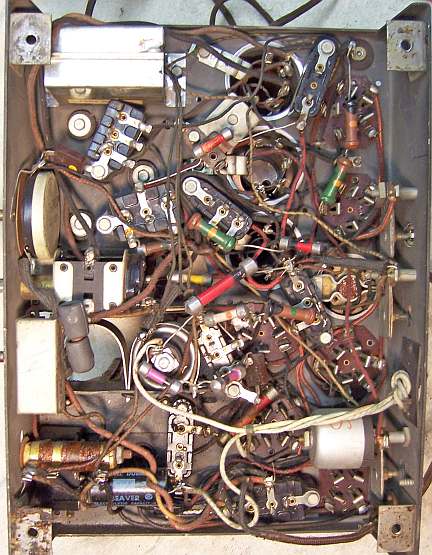
Repairs
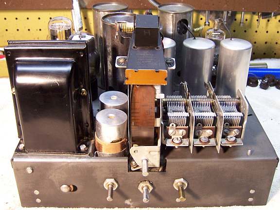
At this point I made BEFORE photos of the chassis bottom. I use these photos to ensure that replacement parts and
wiring are placed as close as possible to their original positions. Some
radios are subject to problems (such as oscillation) if wiring is re-routed or
lead dress is not the same as the original..
All tubes and tube shields were removed. The tuning capacitor and dial
assembly was removed for
cleaning and replacement of chassis grommets and dial cord. All non-original parts were then removed.
The top and sides of the chassis was cleaned with GoJo hand cleaner and 00 steel
wool. Since this process may leave small steel wool fragments that can cause
problems later, I follow up with a thorough vacuuming and go over everything
with a small magnet and masking tape to pick up any stray fragments.
The remaining rivet was removed retaining the type 36 tube socket.
Fortunately I had an original Philco shield base and tube shield in my Philco
parts stock (although they were RUSTY!) The shield base and socket was
then assembled using small 6-32 screws and very small 6-32 nuts.
The tuning capacitor grommets were replaced by GLg-Tuner grommets from Renovated
Radio.
The tuning capacitor was cleaned in an ultrasonic cleaner followed by soap,
water, and toothbrushes. The bearings were then lubricated using distributor
cam lubricant (which is similar to the original grease used). Before
cleaning, the trimmer micas were removed in order to prevent damage. In
order to get the trimmers back to approximately where they were originally set,
I first note the position of the trimmer screw on the clock, then count the half
turns (and fractions) from that position to fully tight. The mica sheets and
trimmer hardware were also cleaned in the ultrasonic cleaner and then dried
before reassembly. After reassembly, each trimmer is again turned to fully
tight position, then backed off the appropriate number of half turns and
fractions. This process will return the trimmers to close to their
original positions (later fixed by a full alignment).
The combination power switch and band switch was removed from the radio and
cleaned in an ultrasonic cleaner using water and dilute ammonia, followed be
soap and water and a toothbrush. After this cleaning both the AC switch
and band switch worked well.
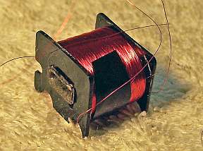
Shadow Tuning Meter
The shadow meter coil was open. I used the service note information found on the Philco
Repair Bench to repair this unit. The meter was disassembled and the
coil removed. I first tried to probe the coil for continuity from the outside using an
Exacto #11 knife blade, hoping that the break would be near the
outside. In that case, it could be restored with minimal loss of
turns. But no luck! So I was faced with rewinding the coil.
The only suitable enamel wire I had in stock was very slightly larger in
diameter than the original. I fabricated a suitable jig to hold the coil
in the chuck of my Unimat lathe, as well as a holder for the supply spool of
wire. The jig consisted of a piece very hard clock pivot wire about
1/16" diameter, plus a couple of wire nails to center the coil. A
wrapping of #22 copper buss wire then secured the nails and wire. The wire
was then chucked in the lathe. The lathe was run at its slowest
speed. I left the belt guard open so I could stop the lathe instantly if
needed. The wire had a tendency to wrap outside the form near the ends.
The
wire did break twice during the rewind operation, but I was able to splice it
back together in both cases. The resulting coil measured 956 ohms vs. 1100
ohms, likely
due to using larger gauge wire. The meter was then assembled and tested using a
variable power supply as suggested in the service note on the Philco Repair
Bench. The meter did function as documented at 10 volts,
and went back to almost zero width at zero volts in. When installed in the radio, the
deflection on-tune was about 1/4" (to about 1/2" off tune). I guessed that this was due to the fact
that I was only using a 20' piece of wire for an antenna (plus I am in a rural
area). A longer antenna, or stronger signals, would have increased the AVC
voltage and thus reduce the plate current and thus the width of the deflection
on tune. But the meter did indeed function!
Resistors and Capacitors
All original Philco bakelite block capacitors were removed from the radio,
their contents removed, cases cleaned, and restuffed using modern film
capacitors. The AVC filter capacitor block, with its two 110pf capacitors, was restuffed using
100pf dipped mica capacitors. One other bakelite block capacitor had a wire wound resistor
inside in addition to a bypass capacitor. This resistor was reused.
All original dogbone and cast end resistors were within
acceptable tolerances and were left in place.
The tone switch capacitor was removed, the insulator salvaged, the two
capacitors replaced, and the case resealed using melted rosin left over from
restoration of RCA superhet catacombs. This wax melts at low temperatures
and will not damaged new components. Some collectors use tinted hot glue
or even caulk for resealing components.
The metal cased bypass capacitor C7, with 5 capacitors inside, was restuffed using new film
capacitors. I was able to salvage the original lead wires and reuse them.
The capacitor consisted of two .09mfd, two .05mfd, and one .25mfd
unit. It was restuffed with two .1mfd, two .047mfd, and one .22mfd film
capacitor. The original insulator inside was retained and reused.
The new parts were sealed using melted rosin.
One original filter capacitor (6mfd) had been removed, and a tubular
replacement installed under the chassis. I had a similar dud in my used
parts collection, and recycled the required cardboard insulator from another dud
capacitor which was the same size. Both the original and replacement duds
were restuffed using 10mfd/450 volt electrolytics. To restuff, the
capacitors were chucked in my Unimat lathe and their cases scored about 1"
from the bottom. The cuts were then completed using a hobby razor
saw. The original contents were then removed and the capacitor case
cleaned inside and out. The remaining original capacitor had a very soft
aluminum threaded stud which was damaged during removal. This was drilled
out and a 10-24 screw substituted, along with a ground lug for attaching the new
filter capacitor. The negative lead of the new capacitor was routed though a
small hole drilled into the hard rubber base and attached to the original ground
lug.
Tubes
The two 44 tubes were replaced by used/tested 39/44 tubes. The 42 tube
was replaced.
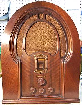
Cabinet
The cabinet only needed a good vacuuming inside and then cleaning on the
outside with GoJo and 00 steel wool, plus
removal of the deteriorated chassis washers. The chassis washers were
replaced using 7/8" x 3/8" washers from Renovated
Radios (CW-4).
Testing and Alignment
Once the radio chassis was reassembled and the tubes installed, power was brought up
slowly using a variac. AC power consumption was monitored using a watt meter, and a
DVM monitored the B+. The radio powered up and worked on both the
broadcast and short wave bands. The radio was then aligned, although all
adjustments were very close to correct.
The radio performs well, and has very good tone. Even the short wave
band works. Perhaps due to the use of 10mfd filter capacitors instead of
the original 6mfd, the B+ is higher than specification even with only 110 volts
AC input! So this radio, like most others in my collection, will only be
operated using my bucking transformer.
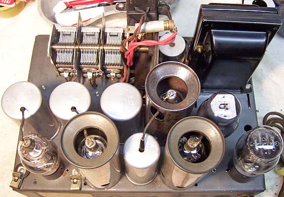
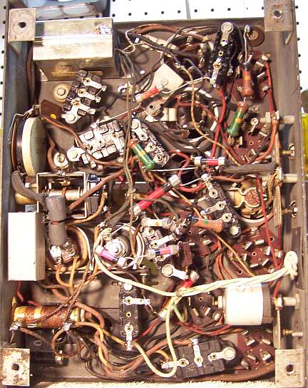
Restoration Results
Chassis Bottom Before and After Restoration