Philco 20B Cathedral Restoration
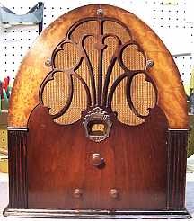 |
The Philco 20B is a large 7-tube rounded top TRF circuit radio dating
from around 1931. It only receives the broadcast (medium wave) band. My
example is the later version of the Model 20. The radio had seen
minimal servicing in the past and most original
parts were still in place. This being the case, I
decided to try to retain the original top and bottom chassis appearance if
possible, yet get it working and replace all capacitors, check resistors
and tubes, etc. for long term reliability.
A schematic and parts list, as well as a parts placement diagram can be
found online at Nostalgia
Air. A more useful schematic, with annotated parts values, can be
found at Philcoradio.com
(late version).
|
My
antique radio restoration logs
Condition As Found
The radio was purchased at the 2014 CC-AWA Conference and Flea
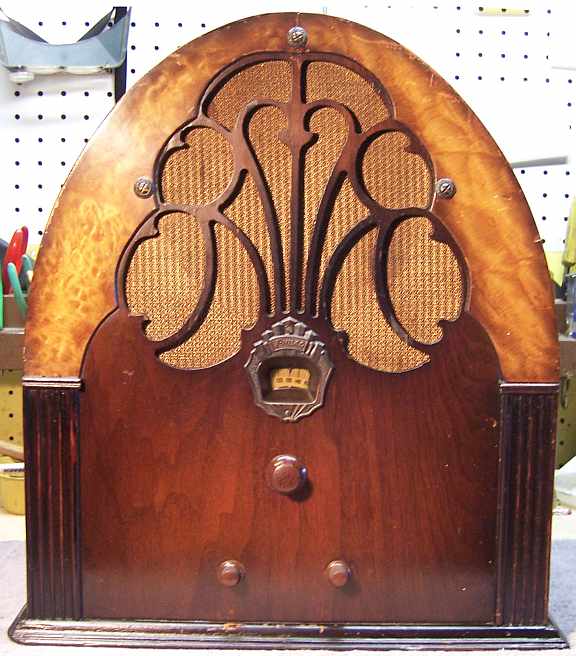
Market, in Charlotte, in the old equipment auction. The radio is the
"Deluxe" version of the Philco Model 20 which has decorative curly
maple trim around the grille area. There was no external sign of any servicing
or restoration having being
done. The cabinet finish, grille cloth, power cord, and knobs appeared original. I always avoid
purchasing a radio that has been "restored" by a collector or flipper,
since they may take shortcuts such as discarding the original capacitors. I
prefer to "restuff" the original parts in order to preserve the
original chassis appearance. To me, radio restoration is a hobby - not a
business - so time is not a factor. I did not attempt to power up the radio
prior to servicing. It was likely working as found! The model 20 uses paper type
filter capacitors rather than electrolytics, which would have dried up or
possibly failed after 80 years.
Previous Servicing
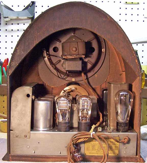
When
I nervously pulled the chassis for inspection. I was pleasantly surprised. There
was no sign of any restoration or servicing having been done (other than tube
replacement). All the original parts looked to be in place. Even the cloth
covered power cord was original, and in good condition. The power plug
looked like an older replacement.
-
All filter, paper, and bakelite block capacitors
were original. However, once I began removing the Philco bakelite block
capacitors for restuffing, it was discovered that one of them (part 19 - the
audio coupling capacitor) already had been restuffed using a new 630 volt
film capacitor. The part had then even been resealed with some sort of wax
(likely beeswax). I doubt that a service shop would have gone to the
trouble.
-
All resistors were original.
-
Three engraved base globe type 24 tubes were installed.
Their original Philco paper labels were still in place, and their date codes
1H (1931?) indicated that they were likely original. The type 71A audio tubes were globe types, but
were not original. They were branded Majestic. The
27 and 80 tubes were also replacement. They were not globe types, and were
not branded Philco.
Cleaning
The first step was to blow off the dust using an air compressor.
After removal of the tube shield, tuning capacitor and filter capacitor, the chassis and remaining top components were cleaned using GoJo,
00 steel wool, and various small brushes.
Survey
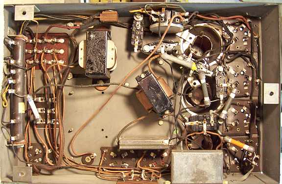
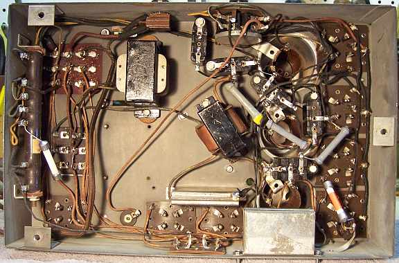
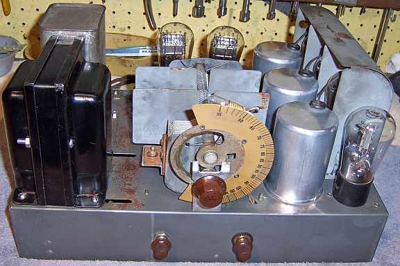
My usual restoration procedure is to take photos of the original
chassis top and bottom for future reference. I then make a complete
survey of the condition of all components and repair all items before the radio
is tested. I assume that all paper and electrolytic capacitors are leaky and thus should be
replaced (I always "restuff" the original components if possible). I
do not replace mica capacitors, but may test them in place if possible.
-
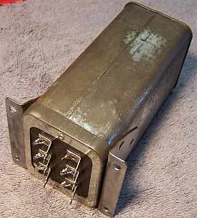
The power transformer was OK. The high voltage was balanced
on each side of the center tap with 10 volts applied to the primary through
a variac. It drew less than 10
watts at full line voltage (unloaded), and all filament voltages were correct.
I always make this test prior to restoration, since some transformers may
have shorted turns which may result in overheating after usage.
-
The speaker field coil, cone, and voice coil were OK.
-
All RF coils were OK (all were tested for resistance and/or
continuity).
-
The audio driver transformer, output transformer and filter
choke were OK.
-
The original cloth covered power cord was OK.
-
The original speaker cable was OK. There was some damage near the
plug. This was likely due to the radio being shoved against a wall (the
speaker plug projects past the cabinet when plugged in).
-
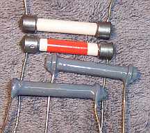
All resistors were old style dogbone types. Some were
cast metal-end dogbones. Four were more than 20% out of tolerance.
-
The type 80 tube showed a short (it was not original). The
three original Philco engraved base globe type 24 tubes were good! All
remaining tubes were also good.
-
The large wire wound resistor was fortunately good. It
would have been very difficult to replace this resistor without grossly
changing the under chassis appearance.
-
Both sections of the volume control measured the correct
resistances. But the wiper for one of the sections did not show continuity
with the resistance element on one extreme end of rotation. This is likely
due to dirt or hardened grease. I decided to wait until the radio was
restored to see what, if any effect this would have. I did not want to
disassemble the control unless I had to. There is really no suitable
new replacement part available, and circuit changes have been published to
allow the use of a standard part.
Restoration Strategy
Since almost all of the original parts were still in place, and
since this was going to be a "keeper", I decided to try to retain the
original top and bottom chassis appearance to the extent possible. All
original capacitors would be rebuilt in their original containers (restuffed),
including the distinctive Philco bakelite block capacitors, the original
filter capacitor, and the metal cased bypass capacitors 13 and 14. Any out of tolerance
resistors would be replaced with the same types if available (otherwise
reproductions).
Repairs
Resistors
The radio uses
"dogbone" type resistors. Most of of them were the older
"cast end" type with solid metal ends. One was the later
"wound end" types with the radial component leads wound around the resistance
element and then soldered together. Four were hopelessly out of tolerance
and would have to be replaced (parts 12, 15, 17, 20).
In most cases,
I would replace an original resistor only if it was not within +/- 20% (or
marked tolerance). One resistor (part 18) measured about 26% high, but it
was not in a critical position and was left in place. I normally replace any "dogbone"
resistors with the same type resistor if available.
I keep a stock of NOS and used "dogbone" resistors, and buy all I can
on eBay and radio swap meets! Of course, most of these resistors, even NOS resistors,
would have also
drifted in value and no longer have their marked values. My solution is to
find a replacement resistor of the correct value and size as measured (ignoring the
markings), and then repaint it to the needed value codes using enamel hobby
paint! Lead length is also considered, as some replacement resistors
need long leads.
I was able to find suitable resistors in my
stock of "dogbone" resistors for most replacements. But in a couple of
cases I was forced to use wound end dogbones for replacements rather than the original
cast end types. I have observed other Philco radios of this age that use a
mix of types. The color coding scheme used in this radio was unfamiliar to
me. The normal color coding scheme used for dogbone type resistors is
body-end-dot (1st digit, 2nd digit, multiplier). But in this case another scheme
was used. In one case, there was a single wide orange stripe in the center of the
resistor (part 12, 50K). Solid gray was 500K (parts 17 and 20). Solid gray with
a yellow end was 100K (part18), and plain white ceramic (no paint) was 250K (part 15). The
original paint on the replacement resistors was removed using lacquer thinner,
leaving a plain white ceramic body for the cast end types. Here are the
replacement resistors:
Capacitors
All the capacitors used in the Philco model 20 are paper type
capacitors - no electrolytics are used. All capacitors were rebuilt in their
original cases using new film capacitors. Three types of capacitors are
used: the normal Philco bakelite block capacitors, metal cased bypass capacitor
blocks, and the filter capacitor block.
Metal Cased Bypass Capacitors
These capacitors are very easy to rebuild. Metal tabs retain a
fiber cover. The common ground connection is soldered to the metal case.
Once this connection is unsoldered, the contents can be easily removed by
straightening the retaining tabs, removing the fiber cover, and then removing
the old capacitor which is wrapped in a fish paper insulator. I keep
the fish paper insulator and re-use it. The original leads were unsoldered
from the old capacitor and were re-used also. Because of space limitations
(width) some new 630 volt film capacitors were too large (I normally only stock
630 volt axial film capacitors). For part 13 (0.5mfd) I used a 0.47mfd/400 volt
radial film capacitor I had in stock. For part 14 (two 0.25mfd units) I used two
0.1mfd/630 volt axial film capacitors for one unit and my remaining 0.47mfd/400
volt radial film capacitor for the other. New radial film capacitors are
much smaller than the axial units.

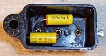
Filter Capacitor Block
The filter capacitor originally contained four paper capacitors:
two 1mfd, one 1.5mfd, and a 0.13mfd. I used two 1mfd/630 volt, a
0.15mfd/630 volt, and a 2.25mfd/630 volt for replacements. There is plenty of
room inside the case once the original contents are removed. The new parts can
be installed on the back side of the terminal strip. The problem is getting the
original parts removed - they are buried in tar! If smaller radial film
capacitors are used, it is likely possible to mount these on the terminal board
without having to remove all of the tar and contents. On a previous model 20
restoration I used heat - which was very messy! The cover with its terminals
were first removed. The leads from the terminals to the capacitor were
then cut. The capacitor was then placed one an old baking tray covered with foil
in an oven at 275 degrees for about one hour facing downward (propped up using
wooden supports). Most of the tar ran out. I then had to dig out the capacitors
and clean up the tar! This time I decided to try using mechanical methods
without heat. As much tar as possible was first removed using a variety of
tools. Once the capacitor foil packs were exposed, I was able to dig them
out. Once one thin one was removed, that left space to manipulate the
other ones. A heat gun applied to the case softened the tar permitting
removal of the capacitor packs - one at a time.
 |
|
Rebuilt Filter Capacitor |
Bakelite Block Capacitors
All original Philco bakelite block capacitors were removed from the radio,
one at a time, making careful notes of connections, their contents
removed, cases cleaned using lacquer thinner, and restuffed using modern 630
volt film capacitors. Before removing the contents I unsolder the internal
capacitor leads from the outside terminals and clean off the terminals. I use
mechanical methods of removing the bulk of the potting tar and capacitors (small
screwdrivers). One must be careful NOT to pry against the bakelite case,
as it is easily broken. Some collectors use heat to remove the contents.
Here is an example of a restuffed bakelite block capacitor from another
Philco restoration:
Other Repairs
The type 27 first audio amplifier tube was replaced with a type 227 globe
type. The defective 80 rectifier was replaced by a type 280 globe
type. Both were RCA engraved base types. The originals or course
would have been Philco branded. All original tubes would have been globe type in
1931.
Cabinet
The cabinet was in excellent shape. It was cleaned with GoJo hand cleaner
and 00 steel wool. There was almost no dirt or any oxidized finish
removed. I suspect that the cabinet previously had been cleaned and
possibly sprayed with some sort of finish, possibly lacquer. The original
patina, grain filler, and stain remained - the cabinet had not been stripped or
refinished.
Testing
After the radio was completely reassembled, power was applied through a
wattmeter and fused Variac. Power was brought up slowly while monitoring
the B+ voltage and the wattmeter. The radio came alive
immediately. The radio was then aligned. Alignment is
straightforward with only three adjustments. I did make the mistake of
aligning the set out of the cabinet. When tested in the cabinet, the dial
pointer (on the escutcheon plate) did not line up with the frequency on the dial
scale. So I had to redo the alignment with the radio in the cabinet.
Restoration Results
Most of my restoration objectives were met, but not all. There was no
intention of restoring the set to factory new appearance! My objective is
usually to reverse any prior servicing and make the radio appear to have never
been repaired. I do not go so far as to artificially "age"
solder joints, as do some collectors! Nothing gives away a restoration
faster than bright and shiny solder joints. Here are some of my
"misses":
- Two replacement dogbone resistors were not the same type as the
originals.
- The existing power plug was re-used. I have no idea what type would
have been used originally.
- Only three tubes were branded Philco (and were likely original).
Chassis Before Restoration
After Restoration Photos
