Philco Model 70B Cathedral Restoration
|
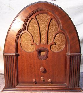
The Philco 70B Cathedral from circa 1932 is a 7-tube superhet with
an RF amplifier stage. This example is the early version, without
AVC.
The radio had seen minimal servicing in the past - all of the original parts were still in place. I decided to try
to maintain the original above and below chassis appearance and to reverse
all previous repairs to the extent
possible. The schematic for this radio can be found on-line at Nostalgia
Air. |
My
antique radio restoration logs
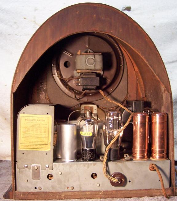
Condition As Found
This radio was purchased on eBay. The cabinet was in very
good original condition, as were the
knobs and grille cloth - just the usual wear, dings and scratches (and nails
through the top holding the brace underneath - has no one heard of glue?
This is my second Philco 70B with those same "repairs"). There was no evidence that the radio had been
restored. Even the line cord was original, and a nasty break resulting in
a dead short would have
prevented plugging it in to "test it", thus avoiding potential
damage. I always avoid knowingly purchasing a radio
that has been restored by a collector, as many take shortcuts such as removing
the original Philco bakelite block capacitors and filter capacitors. There
was some damage to the base moldings on both sides that occurred in
shipping. The seller did not adequately pack the radio, and used a moving
box rather than a shipping box - the box was not much bigger than the
radio! It was fortunately to have survived without major damage. The
damage to the base moldings was repairable.
Previous Repairs
-
Most if not all tubes had been replaced. About half
were globe types, as would have been installed originally. And even
though some tubes, including globe types, were branded Philco, their date codes indicated
vintage 1935 or 1936. So
even these were replacements. Only one tube, a Philco type 24 globe
(RF amplifier) looked original and had a date code of 18, which could be
1931. Some tubes had service shop test result tags, also indicating
mid 1930's in most cases.
-
Two paper capacitors had been tacked in. One of the
lugs on one bakelite block capacitor (part 12) had been removed to facilitate using a
replacement capacitor for one of the two 0.09mfd sections. Fortunately, the original bakelite block was
still in place.
-
The two original copper Mershon filter capacitors were still
in place!
Survey
My usual restoration procedure is to first make a complete
survey of the condition of all components. The survey results guide my
restoration strategy. If major and unique components are defective or
missing and
cannot be restored or replaced, I may elect to sell the radio rather than restore it.
I always assume that all paper and electrolytic capacitors are leaky and thus should be
replaced (I always "restuff" the original containers if possible).
Any mica capacitors are assumed OK until testing proves otherwise.
-
The rotary AC power switch was bad (it measured high resistance) - dirty and/or oxidized contacts
were likely.
-
The rear section of the ganged volume control was open (the 5,000 ohm section that
shunts the antenna coil). These controls cannot be replaced using modern
parts, although some collectors have modified the circuit to use a single
potentiometer. This would be a showstopper if it cannot be repaired.
-
The tuning capacitor grommets were bad - typical of the age.
-
The rubber chassis washers were bad - again typical.
-
The speaker field and cone was OK.
-
The output transformer was OK.
-
The power transformer checked out OK. Power consumed at no load was
very low (measured using a watt meter), all voltages were correct, and the
high voltage was balanced on each side of the center tap.
-
The first detector RF transformer had an open primary winding. Another
potential showstopper. The
remainder of the RF and IF transformers, the RF choke, and filter choke were OK.
-
All tubes were good.
-
The power cord looked original and in good condition, but had one break.
The plug had been replaced.
-
Three original dogbone resistors were out of tolerance.
-
Almost all wiring in the radio was cloth covered and was OK. The
rubber covered wire to the tone control capacitor was flaking off and would
have to be replaced.
Repairs
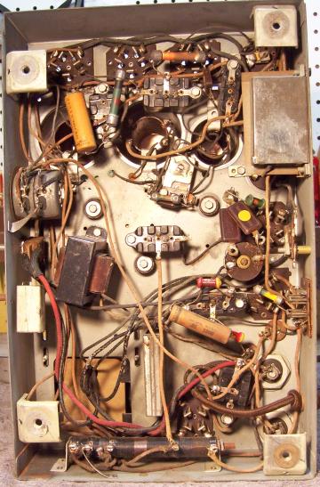
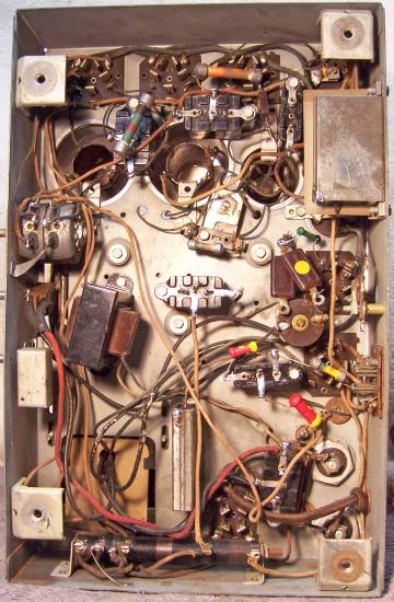
At this point I made BEFORE photos of the chassis bottom. I use these photos to ensure that replacement parts and
wiring are placed as close as possible to their original positions. Some
radios are subject to problems (such as oscillation) if wiring is re-routed or
lead dress is not the same as the original..
All tubes and tube shields were removed. The tuning capacitor and dial
assembly was removed for
cleaning and replacement of chassis grommets. The two copper Merchon
filter capacitors were removed for polishing and restuffing. All non-original parts were then removed.
The top and sides of the chassis was cleaned with GoJo hand cleaner and 00 steel
wool. Since this process may leave small steel wool fragments that can cause
problems later, I follow up with a thorough vacuuming and go over everything
with a small magnet and masking tape to pick up any stray fragments.
The tuning capacitor grommets were replaced by GLg-Tuner grommets from Renovated
Radio.
The tuning capacitor disassembled and then was cleaned with soap,
water, and toothbrushes.
The rotary power switch was removed from the radio and cleaned using
Big Bath cleaner. After this cleaning switch worked well.
Volume Control
The volume control on non-AVC Philco 70s is a ganged wire wound
control. The front section is about 250 ohms and is used to control the
bias of the RF and IF amplifier tubes. The rear section is 5000 ohms and shunts the antenna
coil primary. The rear section was open. The control was removed
from the set and the rear section removed for inspection. The control is
held together with a tough fish paper retainer, and the two sections are linked
internally by a fiber insulator. The rear section was removed by removing
a nut and washer on the back and carefully removing the fish paper
retainer. The break in the windings was between two sections with
different wire sizes and types. The coarse wire provides a slower change
in resistance on the low end of the control. The wire sections were likely
originally linked by welding. The weld had likely broken. I have had
repair success in the past by using a thin piece of sheet brass - almost paper
thin, and used for construction of model railroad equipment. A piece was
first sanded until bright and then cleaned. A piece about 1/8"x3/8"
was cut using scissors. This piece was then inserted between the
resistance wire and the outer insulation - across the gap between
sections. The repair was successful - the rear section now measured about
5000 ohms.
First Detector Transformer
The primary of the first detector RF transformer was open. Examination
indicated "green disease" - corrosion of the wire, which is very
common in Philco radios. The first
thing I tried was to start unwinding the wire until a break was found and then
to repair the break. But the wire was too far gone and was falling apart
and further breaks would occur as it was unwound. So the primary was rewound. I first estimated the number of
turns needed and the wire size. Also noted was the winding
direction. There were about 50 turns on the coil (the
exact number of turns is not critical). The wire was about #38 cotton
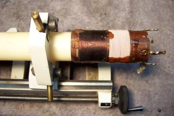
covered. Fortunately I had a roll of suitable wire available. I
fabricated a jig to hold the coil form level and permit rotation, so that the
wire could be wound evenly. The jig consisted of a piece of PVC thin wall
plumbing pipe that just fit inside the end of the coil form (about 12"
long). The other end of the pipe was chucked into my Unimat small
lathe. The end of the pipe with the form attached was supported using my
lathe's steady rest. The drive belt was removed so that the lathe could be
turned by hand. The source wire spool was supported using a wooden dowel
with wood screws in each end, supported by a piece of strapping screwed down to
my work bench. This permitted me to rewind the coil evenly with no gaps
between turns, and no overlaps. Once complete, the winding was secured
using some melted rosin salvaged from servicing RCA early superhet catacombs!
Resistors and Capacitors
All original Philco bakelite block capacitors were removed from the radio,
their contents removed, cases cleaned, and restuffed using modern film
capacitors. One other bakelite block capacitor had a wire wound resistor
inside in addition to a bypass capacitor. This resistor was reused.
The tone switch capacitor was removed, the insulator salvaged, the capacitor replaced, and the case resealed using melted rosin left over from
restoration of RCA superhet catacombs. This wax melts at low temperatures
and will not damaged new components. Some collectors use tinted hot glue
or even caulk for resealing components.
The two metal cased bypass capacitors 29 and 36 were restuffed using new film
capacitors. I was able to salvage the original lead wires and reuse them.
The original insulator inside was also retained and reused. These types
are very easy to rebuild by straightening the metal tabs, unsoldering the ground
lead from the case, freeing up the contents by passing a thin blade between the
insulator and metal case, and pull out the contents. The tar covered
capacitor inside was discarded after removing the original lead wire for reuse.
Both original Mershon copper filter capacitors (6mfd) were still in place.
Some collectors have been able to remove the tops of these capacitors in order
to restuff them. I have never been able to do this easily, and did not want to
risk damaging the very nice looking copper capacitors. To restuff, the
capacitors were chucked in my Unimat lathe and their cases scored about 1"
up from the bottom. The cuts were then completed using a hobby razor saw
and cleaned up using an Exacto knife. This leaves only a thin line on the
case - hardly visible. The original contents were then removed and the capacitor case
cleaned inside and out (using Brasso). The original positive foil was removed and the
stud was cut short and then drilled to accept a ground lug and 4-40 screw and
nut. The positive lead of a replacement 10mfd/450volt capacitor was
attached to the ground lug. The negative lead of the new capacitor was routed though a
small hole drilled into the hard rubber base and attached to the original ground
lug.
Tubes
The radio was re-fitted with all globe type tubes, with the exception of the
47 output tube. I did not have a good 247 in stock, and these are very
expensive. I did have a weak 247, and tried it, but the audio was quite
weak with it in place. One replacement 24 was a NOS Philco type 24 globe!
Cabinet
The cabinet only needed a good vacuuming inside and then cleaning on the
outside with GoJo and 00 steel wool, plus
removal of the deteriorated chassis washers. I did not have replacement
chassis washers in stock. I tried all the washers available at Renovated
Radios, but none of them worked. So I simply omitted the chassis
washers. The control shafts were properly centered with no washers
installed. A previous owner had used small nails to secure the cabinet
arch to its support. These were hardly visible, so I left them in place.
Testing and Alignment
Once the radio chassis was reassembled and the tubes installed, power was brought up
slowly using a variac. AC power consumption was monitored using a watt meter, and a
DVM monitored the B+. The radio powered up and worked. The radio was then
aligned. The radio performs well, is quite sensitive and has very good tone.
Restoration Results
Chassis Bottom Before and After Restoration