The schematic for the RCA 4X can be found on Nostalgia Air. Any part numbers will refer to numbers on that schematic.
|
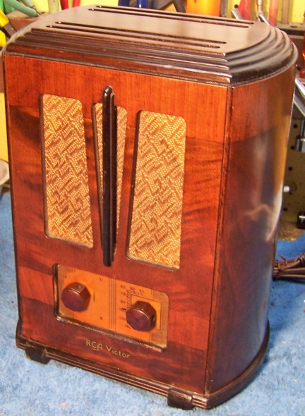
The RCA Model 4X from 1936 is a very compact four tube AC/DC
non-AVC superhet circuit radio. It only receives the broadcast band
(medium wave). It achieves superhet performance using only four
tubes by using two
multi-element tubes: 6A7 oscillator and first detector, and 6F7 IF
amplifier and second detector. The set had seen extensive servicing in the past. The filter
capacitor and all except three wax/paper capacitors had been
replaced. While it would be a challenge, I decided to try to maintain the original top and bottom chassis appearance
and to reverse all previous repairs to the extent possible.
The schematic for the RCA 4X can be found on Nostalgia Air. Any part numbers will refer to numbers on that schematic. |
My antique radio restoration logs
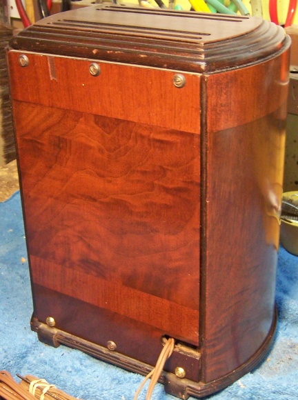
This radio was purchased at the 2012 Antique Wireless Association conference and flea market in Charlotte, NC. It appeared to be in excellent condition with its original knobs, grille cloth, and cabinet finish. There were no external signs of prior servicing or electrical restoration, since the radio is totally enclosed in a handsome wooden cabinet. The antenna hank and resistor line cord were both in place (the line cord did have taped areas). The cabinet had some scratches, and one small veneer chip, but looked like it would clean up and display well.
When opened up for inspection, I found that the set had seen extensive servicing in the past. The filter capacitor and all except three wax/paper capacitors had been replaced. All resistors with the exception of R3 (pilot lamp shunt), including the resistance line cord, appeared to be original. R3 was the correct value and had the correct mounting tabs. However, it was attached to the chassis with a 4-40 screw and nut, which would not have been original. But since wiring to the volume control had been changed, and since this resistor is in the way, perhaps it WAS original and was simply temporarily removed during servicing. All repairs appeared to be older, and likely by a service shop rather than a collector. Many different types of replacement capacitors were used. The work was VERY sloppy, mostly using cut and splice (or just tack!) methods of capacitor replacement. There were wiring errors, and many capacitors had incorrect values. It appeared that the "serviceman" simply grabbed whatever part was available. While it would be a challenge, I decided to try to restore the original top and bottom chassis appearance and reverse all previous repairs to the extent possible.
The original filter capacitor C20-C21 had been replaced by two tubular electrolytics.
Only three original wax/paper capacitors remained. Eight had been replaced by various types, many incorrectly wired and several with incorrect values.
All carbon resistors appeared to be original.
The pilot lamp shunt resistor R3 (wire-wound) may have been replaced (or at least the chassis attachment had been changed).
The tubes were either Sylvania or GE brands. Likely they were not original.
The resistance line cord was original, but was taped in several places (very dangerous!)
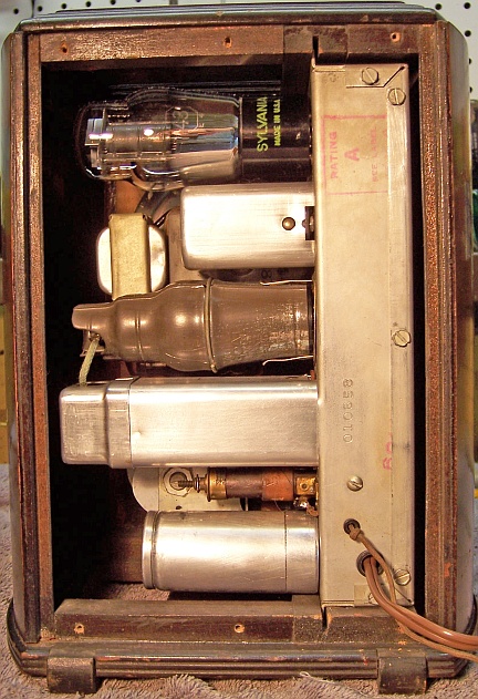
One IF transformer top shield was now missing, likely because if in place the grid cap lead (rubber) would short out!
My usual restoration procedure is to first make a complete survey of the condition of all components. The survey results guide my restoration strategy. If major and unique components are defective or missing and cannot be restored or replaced, I may elect to sell the radio rather than restore it. I always assume that all paper and electrolytic capacitors are leaky and thus should be replaced (I always "restuff" the original containers if possible). Any mica capacitors are assumed OK until testing proves otherwise.
This radio is very difficult to service. The chassis is very compact, and with a high parts count. In many cases, the radio has to be partially disassembled in order to access certain parts. For example, to remove the volume control, the wire-wound resistor R3 has to be partially disconnected and moved to one side. The filter choke has to be detached and also moved aside. Many parts, and especially resistors, are hidden under other parts (capacitors) that have to be disconnected and moved for access.
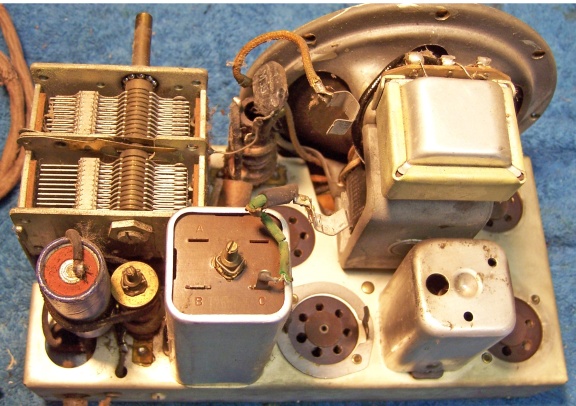
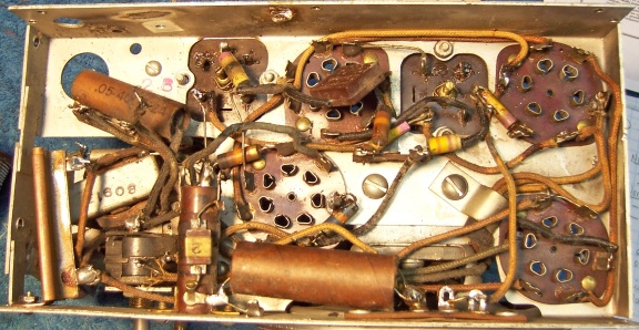
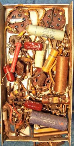
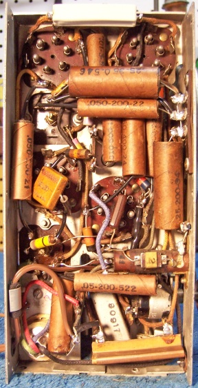
All tubes and shields were removed. Before starting repairs, I took photos of the chassis top and bottom so that routing of wiring and component placement could be restored. Here is the original chassis before restoration:
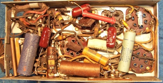
Due to extensive replacement of components, the original lead dress and component placement could not be determined (except for three original capacitors and all resistors). Fortunately, the RCA service information in Riders does include the connection information for all components! I annotated the chassis photo using a red felt-tip pen with the schematic part numbers. I then removed all non-original capacitors, documenting their locations and connections. Here is the chassis with all non-original parts removed:
When I replace a component, I always remove the original part completely from a terminal. Other components connected at the terminal are protected from heat using old medical clamps (hemostats). Excess solder is then removed using a solder sucker in order to expose terminal holes for reattachment of the rebuilt or replaced component. In this radio, due to prior sloppy servicing, most terminals also had wire stubs from replaced components still attached. These were removed. RCA/GE terminals, both on tube sockets and on terminal strips, are difficult to work with. They consist of three tabs, originally separated by a gap. Wiring or components were inserted in the gap, and the tabs then squeezed together and the connection soldered. The problem is, that if not VERY careful, when the joint is de-soldered, and one attempts to spread the tabs apart to either remove or install replacement wires or components, one or more of the tabs will break off! One must work carefully and slowly, and bend the tabs only the MINIMUM amount.
The tuning capacitor, antenna coil and wave trap coil were removed. The top of the chassis was cleaned with GoJo hand cleaner and 00 steel wool. Since this process may leave metal residue, I then went over the chassis with a vacuum cleaner followed up by a small magnet and masking tape. The tuning capacitor was cleaned in an old Heathkit ultrasonic cleaner with dilute ammonia. After drying, the ball bearings were lubed with distributor cam lubricant.
All small resistors in the set were older carbon composition types rated from 1/10 to 1/4 watt. But they were all roughly the physical size of vintage 1 watt resistors. Value color coding schemes varied. One was similar to modern resistors (three stripes), but the rest used a different scheme: body (first digit), end (second digit), stripe (multiplier). Some of these resistors also had a gold stripe on the opposite end (tolerance?) All resistors that needed to be replaced were replaced using modern 1 watt carbon resistors with their bodies repainted using hobby enamel paint. The body/end/stripe coding was used for all replacement resistors.
The first IF transformer (L6-L7) was removed in order to replace two resistors inside its shield can. One (R6) had drifted out of tolerance, and the other (R10) had burned (remnants still intact) and had been jumpered by a piece of solid wire (this of course, screwed up the bias on the output tube!) These two resistors were replaced using modern carbon composition resistors, since they are hidden and not visible.
The volume control and switch was replaced by the correct part as recommended for this model in the IRC replacement guide (D16-116, with a #41 switch). Fortunately, I had these parts in stock! A 330 ohm fixed resistor was placed in series and hidden in spaghetti tubing (the original control had a 330 ohm fixed or minimum resistance section - the replacement did not).
The original line cord resistor R14 (153 ohms) was severely worn and damaged and not usable. In order to reduce the heat that would be dissipated inside the cabinet if an equivalent resistor were installed, I decided to use a diode to reduce the line voltage to the filaments. A diode in series with the tube filaments will reduce the voltage by a factor of 0.707, or to about 85 volts. The tube filaments and pilot lamp together require 68.6 volts. This means that only about 15 volts needs to be dropped, at 300ma. Thus an additional 50 ohms resistance is needed. The power dissipation is only 4.5 watts. So only a 10 watt resistor would be needed. Minor changes to the wiring was necessary to accommodate this change. The 1N4007 diode was hidden in spaghetti tubing and connected between R3 (the pilot lamp shunt resistor) and an adjacent extant terminal strip which had the needed connection to the unswitched side of the AC line. The 50 ohm resistor was inserted in the filament string between the 25Z5 and 43 tubes (the extant lead was simply cut and the resistor spliced in). Before the bottom chassis cover was attached, the 50 ohm power resistor was wrapped with a sheet of asbestos insulation to prevent shorts.
The three original wax/paper capacitors remaining were rebuilt in their original cases using modern 630 volt film capacitors in order to maintain the original under-chassis appearance. The original RCA capacitors have crimps on both ends, and are not sealed with wax. To restuff them, I remove the crimp from one end using a new single-edge razor blade, remove the contents, insert the replacement capacitor wrapped in strips of paper towel to center and stabilize it, then reseal the cardboard tube using rosin salvaged from servicing RCA Radiola Superheterodyne catacombs (it melts at a low temperature and will not damage the replacement capacitors). The capacitor is held vertically in a bench vice, is filled almost full with the melted rosin, and the original cardboard disc which was removed is replaced (the rosin holds it in place). At first, I attempted to remove the crimp on one end and then restore it after restuffing. But this did not work well - leaving a messy result. If the capacitor required leads longer than the new capacitor inside, solid wire of the correct length was soldered to the replacement capacitor prior to restuffing. Some capacitors in this radio need quite long leads!
Eight original wax/paper caps had been replaced in prior servicing. I collect RCA/GE, Zenith, Philco and other branded dud paper capacitors for this exact situation. I was able to find original RCA/GE dud capacitors in my parts stock which had the correct values that matched the schematic and were identical to the types of the three original capacitors found.. RCA/GE wax/paper capacitors of this vintage are simple cardboard tubes with crimped ends. They are marked only with the capacitance, voltage, and a suffix number. There is no brand or manufacturer indicated. The part numbers in the schematic seem to have no relationship to the numbers on the capacitors. Also, the schematic does not mention the voltage rating of any capacitor used! For the replacement dud capacitor cases, I used mostly 200 volt units since this is an AC/DC radio. The line bypass capacitor was original, and rated at 400 volts. All replacement capacitors were restuffed using 630 volt film capacitors.
The original filter capacitor can (C20, C21) was missing and had been replaced in prior servicing. However, I had a Philco screw base can type capacitor in my parts stock which had the correct diameter and approximate length. The original capacitor was a dual 16mfd unit (I assume at 150 volts, since this is an AC/DC set). It had four leads: two for each capacitor. The color coding of the leads and their connection appears on the schematic. The replacement can capacitor was restuffed using two 22mfd 160 volt capacitors. The can was scored deeply about 1" up from its base on my small Unimat lathe, and then cut in two using a Exacto hobby razor saw. New lead wires were attached. The lead wires were setup with the original colors per the schematic. The two halves of the case were rejoined using a 3/4" PVC plumbing coupling and epoxy. Several layers of masking tape were applied to the outside of the PVC coupling to improve the fix inside the capacitor can halves prior to applying epoxy.
One rubber covered grid cap lead and one other lead had deteriorated and was replaced. All other wiring in the set was cloth covered and in excellent condition. However one must be very careful if any of the original wiring is moved - the insulation is very stiff and will break. The original antenna hank was left as it was, even though bare in spots. It was left rolled up on its original form and not extended. The antenna for testing the radio was simply attached to the end of the original antenna.
Once the radio was reassembled and the tubes installed, power was brought up slowly using a variac. AC power consumption was monitored using a watt meter, and a DVM monitored the B+. The radio came alive immediately and worked. The set was then aligned. The only problem found was that the first detector trimmer did not peak up properly (it was left wide open). The radio worked well and picked up lots of stations using only a 20' piece of wire in my basement - pretty good for a 4-tube non-AVC superhet! A better 6F7 tube might have improved performance.
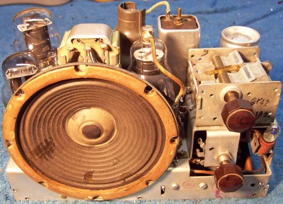
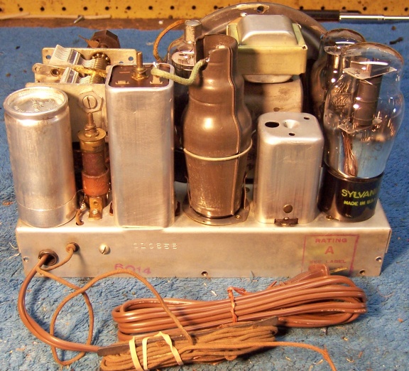
The radio could NOT be restored to original (factory) condition since several parts had to be replaced: the resistance line cord, filter capacitor, and volume control. There was really no place to hide the 10 watt resistor needed to drop the filament voltage, and minor changes to the wiring had to be made. The filament drop diode used was hidden in spaghetti tubing, as was the 330 ohm resistor in series with the center of the volume control (the original control, which was defective, had a minimum resistance of 330 ohms). Except for three original capacitors, the placement of capacitors was unknown. While I was able to use and restuff original RCA dud capacitors, the original part numbers and voltages used was unknown. I have not been able to obtain an original under-chassis photo of this radio. Here are the before and after chassis photos, as well as photos of the completed radio. I was finally able to obtain the missing IF transformer cover seen in the next to last photo below with back open:
 |
 |
 |
 |