The schematic for the RCA 5X can be found on Nostalgia Air. Any part numbers will refer to numbers on that schematic.
|
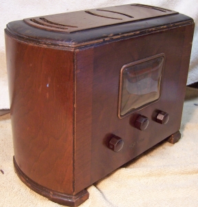
The RCA Model 5X from 1936 is a compact five tube AC/DC superhet circuit radio. It
receives the broadcast band
(medium wave) and one short wave band. The set had seen extensive servicing in the
past, but no collector restoration or shot-gun recapping. While it would be a challenge, I decided to try to
reverse all previous repairs to the extent possible.
The schematic for the RCA 5X can be found on Nostalgia Air. Any part numbers will refer to numbers on that schematic. |
My antique radio restoration logs
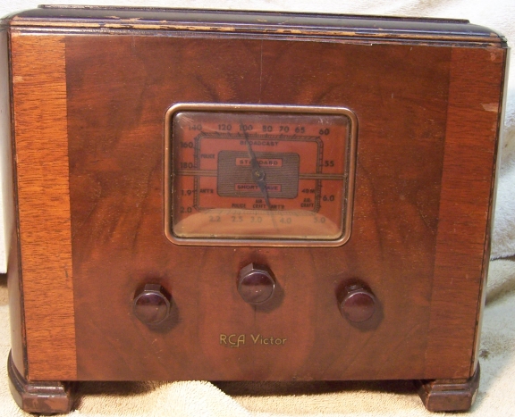
This radio was purchased on eBay. It appeared to be in very good condition with its original knobs, grille cloth, and cabinet finish. There were no external signs of prior servicing or electrical restoration, since the radio is totally enclosed in a handsome wooden cabinet. It was sold as not working. The antenna hank and resistor line cord were both in place (the line cord did have an area with exposed bare wires). The cabinet had some scratches, some veneer loss on the top, and finish loss on the base molding, but looked like it would clean up and display well.
When opened up for inspection, I found that the set had seen extensive servicing in the past. All repairs appeared to be older, and likely by a service shop rather than a collector. Several different types of vintage replacement capacitors were used. While it would be a challenge, I decided to try to restore the original top and bottom chassis appearance and reverse all previous repairs to the extent possible.
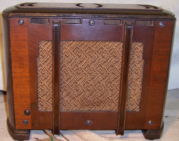
There were at least two versions of this radio produced. One version had an AC line interlock switch, that disconnected all power if the cabinet back was removed. This is a hot-chassis radio - the metal chassis is connected to one side of the AC line either directly (power on) or through the tube filaments (power off). My version did NOT have the interlock feature. Interestingly, my back cover did have the plastic stud that would operate the interlock if present - perhaps all back covers were the same.
As received, the back cover had been installed UPSIDE DOWN! I was more than a little concerned when I noticed that, plus modern screws had been installed to retain the cover. I feared that extra holes had been drilled into the back cover. When I attempted to install the back correctly, it could not be installed because the AC line cord was in the way. The line cord must be routed through an available slot in order for the back cover to fit properly. I suppose that the serviceman could not figure out the routing and routed the cord through the back of the radio and installed the back cover upside down (which meant that some decorative trim pieces stood proud of the top of the radio). Once the line cord was re-routed, and the back cover installed correctly, all the holes lined up - no extra holes had been drilled into the cover (only into the wood behind the cover, which is not visible with the cover attached).
The speaker had been replaced. The original speaker was an electrodynamic type with a 3000 ohm field coil that shunted the B+ input filter. This type of speaker (shunt connected field) is prone to field coil failure due to heat generated and the thinner wire used to wind them. The replacement speaker was a permanent magnet type speaker. Interestingly, the repairman had installed a 2500 ohm 20-25 watt resistor to replace the B+ field coil shunt! This of course, is totally unnecessary, loads down the B+, increases the hum, and generates much extra heat under the chassis.
The original filter capacitor was still in place, but a dual 40mfd/150 volt capacitor had been added in parallel with C23 and C26.
Four original paper capacitors had been replaced: C4, C7, C17 and C20.
All carbon resistors appeared to be original, and were unique in appearance (the parts list indicates they are "insulated" type resistors). They have white ceramic bodies, and their color coding is different than any I have seen before. The insulated construction of the resistors could be because of the very cramped chassis. Normal dogbone type resistors could cause shorts if they contact the chassis, tube socket lugs, or each other.
The tubes were various brands including RCA(2), Sylvania(2), and Delco(1). The RCA tubes may have been original. The radio likely would have been fitted with RCA tubes originally.
The AC plug may have been replaced. Most resistance line cords I have seen had molded rubber integral plugs.
My usual restoration procedure is to first make a complete survey of the condition of all components. The survey results guide my restoration strategy. If major and unique components are defective or missing and cannot be restored or replaced, I may elect to sell the radio rather than restore it. I always assume that all paper and electrolytic capacitors are leaky and thus should be replaced (I always "restuff" the original containers if possible). Tubes and resistors are checked, and Mica capacitors are assumed OK until testing proves otherwise.
This radio is very difficult to service. The chassis is very compact, and has a high parts count. The RCA paper capacitors used are quite large and take a lot of space under the chassis. In many cases, the radio has to be partially disassembled in order to access certain parts. For example, to remove the filter capacitor for restuffing, the oscillator coil had to be moved away from the chassis (it did not have to be disconnected). In order to restring the dial cord, four leads had to be disconnected from the band switch, several other leads disconnected, and the entire dial, antenna coil, wave trap, and tuning capacitor assembly removed as a unit from the radio! Fortunately in my case, the dial cord was OK (but I removed the assembly anyway for cleaning). Many parts are hidden under other parts (capacitors) that have to be disconnected and moved for access.
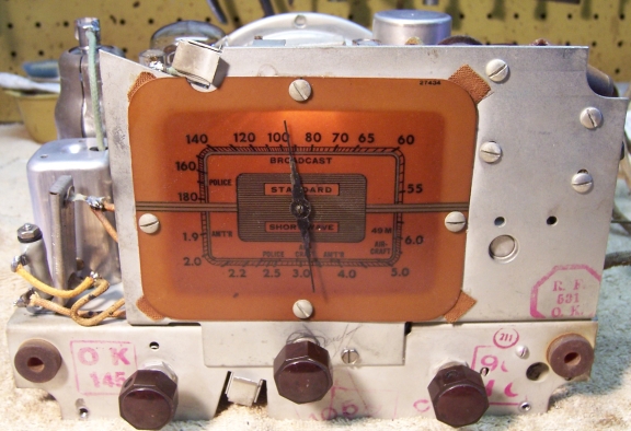
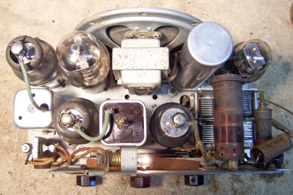
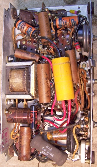
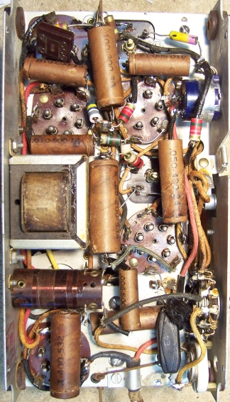
All tubes and shields were first removed. Before starting repairs, I took photos of the chassis top and bottom so that routing of wiring and component placement could be restored. Here is the original chassis before restoration:
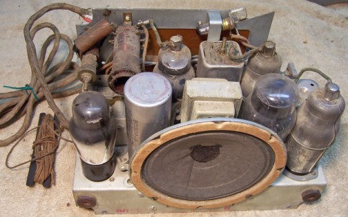
Due to replacement of several capacitors, the original lead dress and component placement could not be determined exactly. Fortunately, the RCA service information in Riders does include the connection information for all components! I annotated the chassis photo using a red felt-tip pen with the schematic part numbers. I then removed all non-original capacitors, documenting their locations and connections.
When I replace a component, I always remove the original part completely from a terminal. Other components connected at the terminal are protected from heat using old medical clamps (hemostats). Excess solder is then removed using a solder sucker in order to expose terminal holes for reattachment of the rebuilt or replaced component. RCA/GE terminals, both on tube sockets and on terminal strips, are difficult to work with. They consist of three tabs, originally separated by a gap. Wiring or components were inserted in the gap, and the tabs then squeezed together and the connection soldered. The problem is that if not VERY careful, when the joint is de-soldered, and one attempts to spread the tabs apart to either remove or install replacement wires or components, one or more of the tabs will break off! One must work carefully and slowly, and bend the tabs only the MINIMUM amount.
The dial, tuning capacitor, antenna coil and wave trap coil assembly was removed as a unit. Instructions for doing this are documented in the RCA service information in Riders. The tuning capacitor was cleaned in an old Heathkit ultrasonic cleaner with dilute ammonia. After drying, the ball bearings were lubed with distributor cam lubricant.
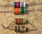
All except one small resistor in the set were older insulated carbon composition types rated 1/4 watt. But they were all roughly the physical diameter of vintage 1 watt resistors but slightly shorter. Value color coding was unique. The body of the resistor was white - I assume ceramic. There was a wide color band on one end which was the first digit. Then a narrow color band followed which was the second digit. The multiplier was a thin color band IN THE CENTER of the first band (first digit). Many of the resistors also had a 4th gold band, which I assumed was tolerance (5%). Approximate reproductions of any out of tolerance resistors were made as follows:
| Here are some original (bottom) and reproduction resistors. I had great difficulty painting the thin stripes! |
 |
The pilot lamp shunt resistor (R15, 40 ohms) was intermittent - its resistance changed when its terminals were moved. This resistor was a Candohm type wire wound metal clad unit riveted to the top of the chassis. I removed it from the chassis and squeezed the metal case near the terminals using my large bench vice. This often restores needed clamping pressure between the terminals and the resistance element, which may shrink over time. The resistor was then stable at about 46 ohms, and there was no leakage to its metal case.
The original line cord resistor R14 (133 ohms) was open, damaged and not usable. Since the break was close to the cabinet, I decided to retain the original cord by cutting it at the break. The built-in resistor would not be used, however. In order to reduce the heat that would be dissipated inside the cabinet if an equivalent resistor were installed (12 watts), I decided to use a diode to reduce the line voltage to the filaments. A diode in series with the tube filaments will reduce the true RMS voltage by a factor of 0.707, or to about 85 volts (AC+DC, which can only be measured using a true RMS meter). The tube filaments and pilot lamp together require 75.2 volts. This meant that only about 10 volts needed to be dropped, at 300ma. Thus an additional 33 ohms resistance would be needed. The power dissipation required was about 3 watts. Only one minor change to the wiring was necessary to accommodate this change. A 1N4007 diode was hidden in spaghetti tubing and connected between the rectifier plates and filament (where the resistance line cord originally connected). A 35 ohm 5 watt resistor was used to drop the remaining voltage. This resistor was attached with a long screw used to re-mount the pilot lamp shunt resistor R15. Since the 5-watt resistor is dissipating 3+ watts, it does get quite hot! But it is mounted on top of the chassis, away from any components.
The original paper capacitors remaining were rebuilt in their original cases using modern 630 volt axial film capacitors in order to maintain the original under-chassis appearance. The original RCA capacitors have crimps on both ends, and are not sealed with wax. They are marked only with the capacitance, voltage, and a suffix number such as .050-400-33. There is no brand or manufacturer indicated. The part numbers in the schematic seem to have no relationship to the numbers on the capacitors. Also, the schematic does not mention the voltage rating of any capacitor used! To restuff them, I remove the crimp from one end using a new single-edge razor blade, remove the contents, insert the replacement capacitor wrapped in strips of paper towel to center and stabilize it, then reseal the cardboard tube using rosin salvaged from servicing RCA Radiola Superheterodyne catacombs (it melts at a low temperature and will not damage the replacement capacitors). The capacitor is held vertically in a bench vice, is filled almost full with the melted rosin, and the original cardboard disc and remaining crimped end which was removed is replaced (the rosin holds it in place). At first, I attempted to remove the crimp on one end and then restore it after restuffing. But this did not work well - leaving a messy result and likely damage to the cardboard tube. If the capacitor required leads longer than the new capacitor inside, solid wire of the correct length was soldered to the replacement capacitor prior to restuffing (the joint is hidden inside the case).
Four original paper caps had been replaced in prior servicing. I collect RCA/GE, Zenith, Philco and other branded dud paper capacitors for this exact situation. I was able to find original RCA/GE dud capacitors in my parts stock which had the correct values that matched the schematic and were identical to the original capacitors in the radio. For three of the four replaced capacitors I found exact originals in my dud stock. In one case I did not have a correct original: C4, which was 0.05mfd. In this case I used an RCA .1mfd dud which was the correct size. To avoid future confusion, I marked the correct value on the capacitor body.
The original filter capacitor can (C23, C24, C26) was still in place. It was rated at 2 x 16mfd at 150 volts and 10mfd at 25 volts. The original capacitor was restuffed using two 22mfd 160 volt capacitors and a 10mfd 50 volt capacitor. The lead wires were replaced. The can was scored deeply about 3/4" up from its base on my small Unimat lathe, and then the cut was completed using an Exacto fine razor saw. Most of the contents were removed (with some difficulty!) using a 1" spade bit in my small drill press. The inside of the can was then cleaned. The two halves of the case were rejoined using a 3/4" PVC plumbing coupling and epoxy. The replacement capacitors were secured with shrink tubing and hot-melt glue inside the PVC coupling.
One rubber covered grid cap lead to the 75 tube was replaced. Replacement of this lead required that the second IF transformer be removed from the chassis and its shield removed. This was a delicate operation, involving removing components and/or wiring from its six lugs. The only alternative would have been to use spaghetti tubing or shrink tubing - NOT NEAT! The 78 tube grid cap lead was cloth covered and not damaged, but was about to break loose from the IF transformer terminal. So it was replaced with the same color cloth covered wire.
All other wiring in the set was cloth covered and in excellent condition. However one must be very careful if any of the original wiring is moved - the insulation is very stiff and will break if disturbed. The frayed and bare wire from the original antenna hank was removed and the remaining good portion spliced to a piece of similar type antenna wire. The original was in several pieces with much bare wire showing.
The original resistance line cord was cut short and reused, but the resistance element was not connected on either end. While currently safe to use, the cord and its cloth covering are very fragile.
Once the radio was reassembled and the tubes installed, power was brought up slowly using a variac. A DVM monitored the B+. The radio came alive immediately and worked. The set was then aligned. Unfortunately, during alignment the dial cord broke! I had to remove the tuning mechanism from the radio yet again! The length of the cord is critical and the distance between the end loops must be exact, within about 1 mm! Obviously, originally a replacement cord which was the correct length would have been obtained from RCA. I was able to fabricate a replacement cord using new dial cord material by temporarily reattaching the parts of the broken cord using super glue. I then installed two small pins into a long piece of wood. The spacing of the pins was exactly the distance between the attachment loops of the original cord. A replacement cord was then fabricated using the pins for spacing. The loops on the ends were knotted and secured with super glue. The replacement cord was then reinstalled. The installation process took about 1 hour of frustrating trial and error! The end of the tension spring (labeled "start" in the diagram) was retained using a rubber band. The most difficult part of the procedure was getting the cord wrapped around and secured on the tuning capacitor pulley.
When the radio is first turned on, the pilot lamp flashes very brightly for a short period of time. This is because the rectifier has no pilot lamp filament tap like later AC/DC radios, which used a 35Z5 rectifier. The the 35Z5 (and 35W4) pilot lamp tap provides a soft start function (and also acts as a fuse if there is a B+ short or severe overload). Since this flash would likely result in the lamp failing quickly, and since it is a real pain to replace the lamps (the chassis must be removed from the cabinet), I decided to install a CL-90 inrush current limiter in series with the filament string. This device provides the needed soft start function. The CL-90 was mounted close to the existing pilot lamp shunt resistor R15 and added 35 ohm filament drop resistor.
The radio could NOT be restored to original (factory - unserviced) condition since several parts had been or needed to be replaced: the resistance line cord, volume control, and speaker. There was really no place to hide the 5 watt resistor needed to drop the filament voltage, and minor changes to the wiring had to be made. The CL-90 inrush current limiter is also visible. The filament drop diode used was hidden in spaghetti tubing. I was able to use and restuff the original remaining RCA capacitors, as well as exact replacements for three missing originals. Only one replacement capacitor was the wrong value, but was the correct type (restuffed with the correct value).
I have yet to find suitable replacement dark bronze cup washers and #4 x 3/4" oval head screws used to mount the back cover. I used 4-40 brass hardware I had in stock and an available brass darkening solution. The result was an acceptable match to the one existing original aged bronze cup washer and screw.
Here are the before and after chassis photos, as well as photos of the completed radio.
 |
 |