The radio had not been restored, and had few repairs. I decided to attempt to maintain the original above and below chassis appearance to the extent possible, yet restore operation.
The schematic for the radio can be found on Nostalgia Air.
|
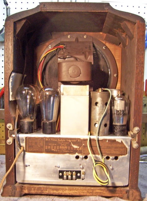
The RCA Radiola R-7 Superette is a circa 1931 8-tube
superhet circuit radio that receives the broadcast band only.
Circuit features include a tuned RF amplifier and push-pull 45 output
tubes. It uses 2.5 volt tubes typical of the early to mid 1930's.
This same chassis is used in other RCA and GE radios, such as the GE S-22.
The radio had not been restored, and had few repairs. I decided to attempt to maintain the original above and below chassis appearance to the extent possible, yet restore operation. The schematic for the radio can be found on Nostalgia Air. |
My antique radio restoration logs
The radio was purchased at the 2012 Antique Wireless Association Charlotte Conference in the auction. As acquired, the cabinet, grille cloth and knobs were original and in good condition. There was some finish loss on the cabinet, but it appeared that the radio should clean up quite well without refinishing. The radio had seen very few repairs in the past. All of the tubes had been replaced at some point, since none of the original RCA globe type tubes remained. The filter capacitors had been replaced with screw-based units, an older repair. The original capacitors were 10uf and 4uf at 450 volts - likely copper Mershon wet types. The replacements were both 8uf dry type capacitors. All of the resistors were original, as were the bypass capacitors. Even the cloth covered line cord and plug was original.
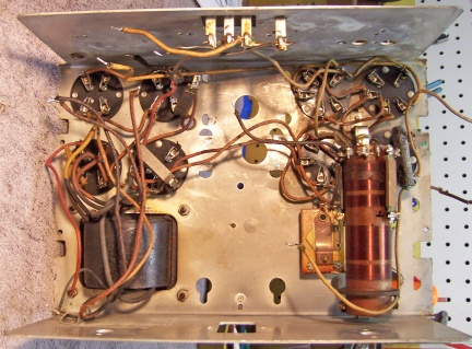
My usual restoration procedure is to first make a complete survey of the condition of all components before starting any repairs. The survey results guide my restoration strategy. If major and unique components are defective and cannot be restored or replaced, I may elect to sell the radio for parts rather than to restore it. I assume that all paper and electrolytic capacitors are leaky and thus should be replaced (I always "restuff" the original containers if possible). This is a very difficult radio to work on. The chassis is packed full, and components must be removed in order to access components below them for testing. The tuning capacitor is UNDER the chassis! The speaker cable needs to be unsoldered from the speaker terminal board before the chassis can be removed - no plug was used! All the bypass capacitors are in a single assembly, sealed in tar inside a metal box. The combination output transformer and audio driver transformer are also sealed in tar inside a metal box. Both metal boxes are attached to the chassis with bent-over metal tabs, which are very difficult to straighten up in the very cramped environment.
The speaker cone, voice coil, and field coil were OK
The output transformer was OK
The audio driver transformer had an open secondary winding (it is sealed in tar along with the output transformer inside a metal container). Actually, only one half of the secondary was open.
The power transformer was OK. The high voltage was balanced across the center tap with 20 volts AC applied. Power draw was very low at full line voltage, unloaded. I use a real analog watt meter for this measurement. A transformer with shorted turns will draw excessive power and will heat up. In this case, unloaded power draw was only about 5 watts.
All RF coils and both IF transformers were OK.
The detector plate choke was OK.
The pilot lamp was OK.
All tube shields were present.
The only wire wound resistor was OK.
All except one original dogbone resistor were hopelessly out of tolerance, which is typical.
Some of the original wiring, and especially grid cap leads, was defective.
It was assumed that the bypass capacitor block would have to be rebuilt.
The AC switch (toggle type) was defective, likely due to dirt and oxidation.
The volume control was open, and there was a part loose inside.
The tone control was intermittent and when rotated past about 50% of rotation, measured open.
All tubes were replacements (ST or shouldered type, vs. the original globe types). One 45, the 80, one 27, and the 24A were good. The other 45, the other 27, and both 35/51's were very weak. Most tubes were branded National Union, and a few RCA.
Before any repairs were made, or any components removed, photos were taken in order to restore any wiring moved or removed to its original position. Lead dress is often important in some radios. Most chassis parts were then removed for repairs and restoration, as well as to clean the chassis:
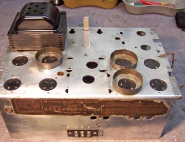
At this point, of the major components, only the power transformer and combined detector and oscillator coil remained in place. Some leaking tar or wax was first removed using mineral spirits. The top and front/back of the chassis was cleaned with GoJo hand cleaner and 00 steel wool. The top of the power transformer was cleaned, the rest of the chassis masked off, and the top of the transformer painted using semi-gloss black spray enamel. Here is the stripped chassis:
 |
 |
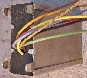
The bypass capacitor block contains seven paper capacitors. Some of the bypass capacitor block leads were disconnected when the resistor terminal board was removed for replacement of the resistors. Other leads were connected to various points on the chassis. It was very important to identify each lead as it is removed. This was necessary since most of the original lead colors had faded. In my radio, most wiring appeared as some shade of orange or yellow. The Riders documentation is excellent for this radio, since it includes a point-to-point wiring diagram for all components, with lead colors identified. You need to know the original lead colors since the wiring to the capacitor block will likely have to be replaced, and thus you need to know the length of each original wire from the point where it exits the capacitor case. A few of the leads retained their original colors. The others were marked using a Sharpie felt-tipped pen, and a cross reference between the number of marks and the original colors was created.
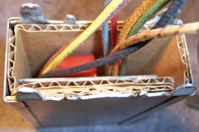
In order to remove the capacitor case I first removed both IF transformers. This gave me space to work, as the bent-over tabs are VERY difficult to straighten up. This was not a wasted exercise since there are components below the IF transformers that would be difficult to access for testing and replacement with the transformers in place. A very sharp screwdriver is needed to start the removal process by straightening up the tabs. Once removed, there is a cardboard cover on the capacitor case retained by bent-over metal tabs. These tabs were straightened and the cover removed. The unit was sealed in tar. The intent was to rebuilt the unit in its original case, using new cloth covered wire leads. The original contents were first removed:
: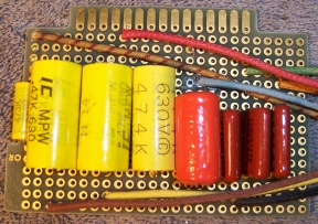
The inside of the metal case was then insulated using cardboard and the circuit board inserted. The height of the cardboard was calculated so as to support the original cardboard cover at the correct height so that it could be re-secured using the bent-over tabs.
The wire leads were passed through the original cover and the tabs bent back to retain the cover. Here is the completed capacitor:
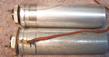
The two can type electrolytic capacitors C17 and C18 were replacements. The originals were likely copper Merchon screw based wet capacitors with a single plus terminal lug. The original ground terminal was used, and it fit the base of the replacement perfectly. These replacement capacitors were rebuilt in their original containers, since I had no clue as to what the originals looked like (and finding originals would be next to impossible). The cans were deeply scored about 1" up from the base using my small Unimat lathe and the cut completed using a hobby razor saw. The original contents were removed, the cases cleaned, new 450 volt electrolytics installed inside, and the two halves of the cans joined using PVC plumbing couplings and epoxy. I also apply a few layers of masking tape to the PVC coupling to take up excess clearance with the can. The original capacitors were 10mfd and 4mfd. I used 10mfd and 4.7mfd replacements, at 450 volts. Small holes were drilled in the hard rubber capacitor bases near the center terminal (for the plus lead of the replacement capacitor) and near the threads of the stud (negative lead). The plus leads were attached to the original center terminal lugs. The negative leads were extended using bus wire and insulated with spaghetti tubing inside the can and passed through the hole near the threaded stud. The negative leads were trapped between the chassis (or ground terminal) and the capacitor when the capacitor was mounted. On C17 (the one with the attached ground terminal) the ground lead was connected to the ground terminal. On C18, the ground lead was routed through an extant nearby hole in the chassis and soldered to the chassis underneath. The rebuilt capacitors are shown below:
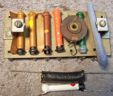
A terminal board contains most of the resistors used in the radio, plus the detector plate RF choke. All of the carbon resistors on the board were severely out of tolerance. The one wire wound resistor (R4) was OK, as was the RF choke. The board was removed from the radio, then the defective resistors removed. All were 1 watt size dogbone type resistors. In order to maintain originality, I wanted to replace the resistors with the same type resistors. I collect NOS and used dogbone resistors just for this purpose. But even NOS resistors would usually also be out of tolerance. In this case, I selected suitable replacement resistors from my stock that were the correct size and had the correct value (at least within +/- 15%), regardless of their color code. I then repainted the replacement resistors with the color codes used for the original resistors, using enamel hobby paint. The terminal board was cleaned, and the replacement resistors reinstalled. Below is the result. Also in this photo are two other resistors that were replaced by reproductions. The 10K resistor on the board was NOS, and was in tolerance (thus not repainted). The blue sand type resistor is wire wound (R4). Many of the resistors on the Riders (RCA) wiring diagram use an older color code. For example, the 1 meg resistor (R9) is noted as green and gray. Its replacement was repainted using this code as seen below. Most other resistors used the more common body/end/dot code.
The audio transformer assembly was removed from the chassis for repair. Like the capacitor pack, it was mounted using bent-over metal tabs, and is equally difficult to remove. It contains both the output transformer and the interstage transformer, and both are potted in tar! The output transformer was OK, but 1/2 of the secondary of the interstage transformer was open, so this transformer would have to be replaced. Before any work was done, each lead was identified (using resistance measurements and in some cases color) and its length measured (from the point of exit from the case). This was needed since the original colors had faded, plus the wiring would likely have to be replaced. In order to maintain the original lead dress and routing, any replacement wiring must be the same length as the original. Even though the output transformer was good, it might be damaged during the process of removing it from the case. So I needed to measure its ratio before attempting removal.
The ratio of the output transformer was measured by connecting the primary to my old HP200A audio oscillator, which can deliver 20 volts or so of a clean sine wave. The 200A was set at 400 Hz. The primary and secondary voltages were then measured, and the ratio calculated. It was 45.6 to 1 (whole primary to secondary). Since half of the secondary of the interstage transformer was OK (as was the primary), it could also be measured. The same procedure above was used. The ratio was found to be 1 to 2.1 (primary to 1/2 secondary). Thus a 1:3 or 1:4 CT transformer would likely work OK.
The transformer case was placed leads up in an old discarded aluminum tray sitting on an old baking tray (which had sides). The transformer was heated in the oven at 275 degrees for 1.5 hours in order to melt the potting tar. The transformers were then removed by gently pulling on the wire leads. They were then left to soak in mineral spirits overnight. Here is the mess right out of the oven!
![]()
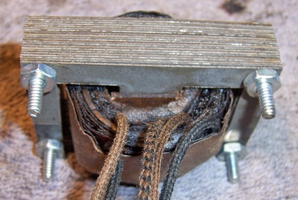
The original output transformer was not damaged and was re-used, along with its original lead wires (except for one frayed lead going to the speaker voice coil, which was replaced). There was tar embedded in the laminations, and the assembly was secured only by a couple of cardboard wedges. There was originally some thick cardboard separators used to secure the transformers prior to pouring in the potting tar. These were not reused. The transformer was carefully disassembled for cleaning. Each lamination layer consists of a long E shape and a short E shape facing each other. On the adjacent layers, the order is reversed for overlap. These laminations were individually cleaned using lacquer thinner, as was the coil and leads. The transformer was then reassembled, the wedges reinstalled, and bolts added in extant holes to hold the transformer together (since the tar would NOT be replaced!) Here is the completed output transformer:
Since there is no audio driver stage in this radio, and the second detector drives the push-pull output stage directly through the interstage transformer, it is important that the transformer have as high an inductance as possible. I have found that using a normal Stancor A-53C type transformer in this circuit results in a high distortion level. I had previously restored a similar radio (same chassis - a GE S-22) and used a Stancor A-63C transformer to replace that radio's open interstage transformer. It worked OK and sounded good (but possibly NOT as good as the original). I wound up using a Stancor A-73C for this restoration. It is much larger, has lots of iron, and thus likely has high primary inductance. Its primary resistance is actually higher (841 ohms) than the original transformer (720 ohms). With its mounting tabs bent straight, it just fit inside the case. New lead wires were attached, since the originals were much longer. Cardboard was used to line the metal case and to secure the transformers. The order of the transformers was reversed: the A-73C was first placed in the case, followed by some cardboard, then the original output transformer. Since its leads were now longer that they were originally, they were cut short after the transformer was assembled.
![]()
The volume control was a wire wound unit. As found, it measured open, and the control shaft would not rotate the full amount. Something inside the case was blocking rotation. The control was first removed from the radio and its back removed (bent-over tabs). The resistance element (nichrome wire wound on a fiber form) was OK. But a metal wedge intended to expand the resistance element against the case was not in place. This blocked rotation of the wiper and also prevented a proper ground connection for the resistance element. This wedge was reinstalled after minor trimming of the fiber form (which must have expanded over time, forcing the wedge out of place). Once this was done, the control worked properly and the resistance was correct. The wedge was soldered to the control case to prevent future problems.
The tone control was a Bradleyometer type control. The control measured open circuit at some point in rotation, and the resistance jumped around as the shaft was rotated. This indicated that the control needed cleaning. The control was removed from the radio and its back removed. The wiper and resistance element were cleaned with lacquer thinner on a Q-tip. Note that the wiper does not directly contact the resistance element, which is wound with circles of wire. I used a minimum amount of lacquer thinner so as not to damage the resistance element. After cleaning, the control worked perfectly.
All tubes were replacements (ST or shouldered type, vs. the original globe types). One 45, the 80, one 27, and the 24A were good. The other 45, the other 27, and both 35/51's were very weak. Most tubes were branded National Union, and a few RCA. Since the cabinet and chassis restoration went so well, I decided to use globe type tubes for the five tubes that were visible and not enclosed in shields: two RCA 245's, a Philco 280, a Silvertone 235, and an RCA 227.
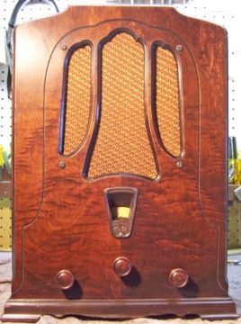
The cabinet was first vacuumed thoroughly and then cleaned using GoJo (white) hand cleaner and 00 steel wool. This was followed by a treatment of Howards Restora-A-Finish (dark walnut) and finally a coat of Johnson's Wax. The wooden knobs were also cleaned using GoJo. The grille cloth was vacuumed - it was in perfect condition.
After completion of restoration, the radio was connected to a variac and the power gradually applied while monitoring the B+. A 50' indoor antenna was connected. The radio came alive and worked well. The bottom cover was then attached and the radio aligned. The sound was OK, but there was some distortion detected on music. This could be due to the driver transformer replacement I used (Stancor A-73C) or simply the type of second detector used (anode bend type). These types of detectors have much higher distortion than normal diode detectors. However the trade off is that they provide needed gain. Also, this radio is a non-AVC set, which is subject to overload on strong signals. The B+ was much higher than specification, even at 110 volts AC input. And the input filter capacitor was the correct value.
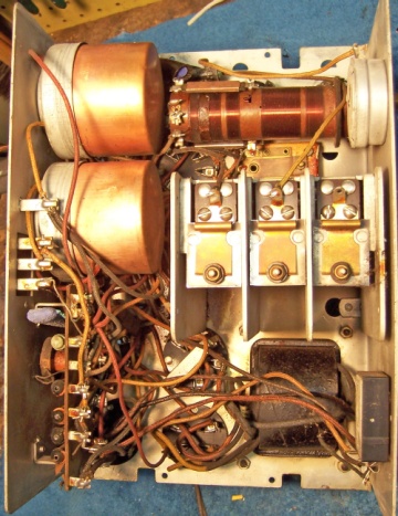
|
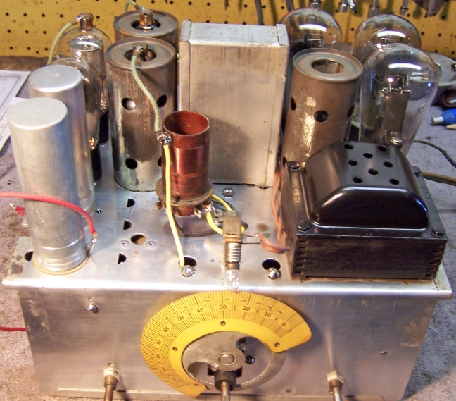
Chassis Before Restoration |
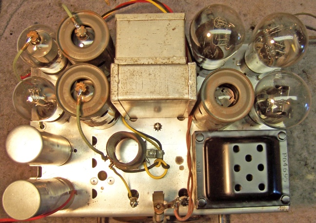
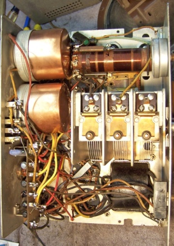
Chassis After Restoration |
 |
 |