The schematic for the Silvertone 1705 can be found on Nostalgia Air. Any part numbers will refer to numbers on that schematic.
|
The Silvertone 1705 is a small six tube AC (transformer
type) table
radio. It receives the broadcast band and one short wave band
(Police Call band - there are no dial markings for this band). The radio had seen
some servicing in the past, and what had been done was done
sloppily!. I decided to try to reverse any previous
repairs to the extent possible.
The schematic for the Silvertone 1705 can be found on Nostalgia Air. Any part numbers will refer to numbers on that schematic. |
My antique radio restoration logs
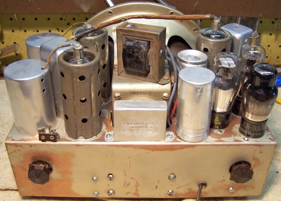
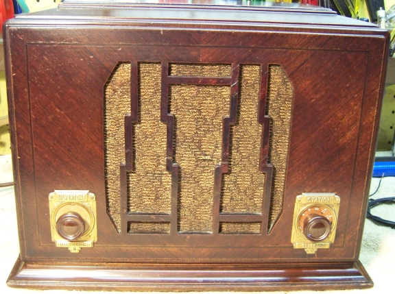
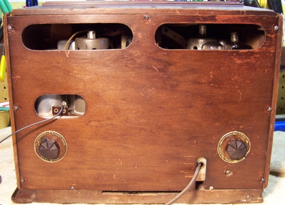
This radio was purchased on eBay. It was sold as working (with issues). After confirming that the filter capacitors had been replaced with fairly modern units, very brief testing confirmed that the radio powered up and made some noises. My example cabinet was presentable, with no damage or serious scratches or dings (a chunk of wood was missing from the bottom rear trim). It had all its original knobs and grille cloth, and the cloth was in good condition. The radio is quite unique in that two of the controls (band switch and tone control) are on the back of the cabinet. The six tube superhet circuit has a tuned RF amplifier stage that is only used for the broadcast band. For the Police Call band, the antenna coil is connected directly to the first detector stage. For its size, the radio has a very large electrodynamic speaker. That contributes to the cramped chassis and difficulty of servicing. Also contributing to servicing difficulty is that the power transformer and tuning capacitor are mounted under the chassis! Here is what the radio looked like originally:
The radio had seen some repairs in the past. It is not known if these repairs were done by a service tech or a collector. The original chassis mounted filter capacitors had been removed and recent tubular replacements tacked in under the chassis. The power cord (and plug?) also had been replaced. It was a recently available cloth covered cord, but had been there awhile. None of the original paper capacitors or resistors had been replaced. For some reason, the leads to the speaker field and output transformer had been extended using several taped splices. I later found out that the speaker would have had to be removed in order to remove the filter capacitors from the chassis. The longer leads were kept and simply reconnected, likely in order to test the radio after replacing the filter capacitors and completing other repairs. The repairs done were very messy and there were at least two wiring errors - the fixed bias to the audio tubes was effectively disabled and the AVC line shorted to ground. Several leads to the bypass capacitor block had been cut, spliced back together, and insulated with electrical tape. Perhaps this was done to test the capacitor? There was also some spaghetti tubing on some of the block capacitor leads. It is not known if this was original. For some unknown reason there was a spring clamp attached to the block capacitor body. The ends of this clamp had been cut off!
A two-piece shield that covered both ends and part of the bottom of the chassis was missing. It was very likely removed for servicing and not replaced. The cabinet feet had been replaced by modern plastic feet attached with screws.
My usual restoration procedure is to first make a complete survey of the condition of all components. The survey results guide my restoration strategy. If major and unique components are defective or missing and cannot be restored or replaced, I may elect to sell or keep the radio for parts rather than to restore it. I always assume that all paper and electrolytic capacitors are leaky and thus should be replaced (I always "restuff" the original containers if possible). Any mica capacitors are assumed OK until testing proves otherwise. Power was applied briefly through a wattmeter and variac and confirmed that the radio did power up and make some noise. So there were no major problems suspected.
The power transformer was OK. The high voltage was balanced across the center tap with 20 volts applied to the primary through a variac. With full power applied (no tubes present), the wattage consumed was less than 10 watts. A transformer with shorted turns will draw excessive power and will heat up. I use a real analog watt meter for these tests. I always check for shorted turns before starting a restoration, since it may take some time before a transformer shows signs of overheating (after the owner has gone to the trouble and expense of replacing all capacitors or even investing in replacement tubes).
All RF coils and transformers were OK.
The IF transformers were OK.
The output transformer and speaker were OK and were working, including the field coil.
The volume control and ganged "power control" potentiometer measured open circuit.
Several escutcheon screws were missing.
The dial scale, which rotates with the tuning knob, was not attached to the shaft. It was not clear how it should have been attached.
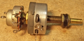
Before starting any repairs, I had to address the potential showstopper issue of the volume control assembly. The volume control (with AC power switch) was ganged to a wire wound "power control". Both the volume control and power control measured open (infinite resistance). Here is the original control:
The power control (front section) was identified in the schematic as 600 ohms "with stop" (which I assumed meant it had some minimum resistance). It varied the cathode bias on the RF and IF amplifier stages, as well as the first detector stage, thus controlling the gain of those stages (all involved tubes are variable mu types). As the volume control is advanced, the RF section bias would be reduced, thus also increasing the RF sensitivity. The power control had a very long front bushing, and would be difficult to replace. The rear cover was removed by unbending four tabs. The wire wound resistance element itself was not open, however it appeared not to be firmly connected to or in contact with the control's terminals. The wiper was also not making good contact with the resistance element due to dry hardened grease. I first attempted a repair by removing the wiper assembly and cleaning it, as well as the surface of the resistance element, using lacquer thinner (the element originally had a thin coating of grease). The wiper assembly was removed by removing the retaining C-clip on the front of the shaft (which is difficult!) But the control still did not work properly and the resistance value was not stable.
Having restored such controls before, I knew that the control's terminals are not rigidly attached to the resistance element, relying only on pressure. So I drilled out the rivet which retained the control's center contact as well as the resistance element. The resistance element was then carefully removed (one must use extreme caution when removing the fiber insulator to avoid breaking it). The two ends of the element are butted together and retained by the rivet and a washer. The expansion of the assembled element plus the rivet and washer provides the pressure between the resistance element and the control's terminals.
All parts of the control were then cleaned in my old Heathkit ultrasonic cleaner using a dilute ammonia solution. The parts were then cleaned with soap, water, and a toothbrush and carefully rinsed. They were then dried using a heat gun. This control was VERY unusual! On the back side of the resistance element, a piece of thin metal (foil of some type) was in contact with the resistance wire for about 1/2 of the rotation of the control from the minimum volume position. Thus, from minimum volume up to about 1/2 rotation the resistance of this control remained constant at about 380 ohms. Then for the next 1/4 rotation, the resistance varied linearly until the physical stop was reached at about 72 ohms. After cleaning and reassembly (the rivet was replaced using a 4-40 pan head screw and nut, reusing the original washer). The control seemed to work OK, although the resistance was lower than specified in the schematic. I hesitated to remove the foil strip for cleaning, since I did not know what type of material was used should it be destroyed when removed. I decided to await final testing of the assembled radio before messing with it. It is likely that the foil was not in good contact with all parts of the resistance wire.
The volume control (rear part of the dual control) was shown in the schematic as 725K ohms with a tap! The tap in this case provided a voltage divider function for the AVC voltage (normally taps are used for tone control)! The value of the tap resistance is not shown in the schematic. The volume control was bolted to the rear of the wire wound power control, had a very short bushing and shaft, and had a slot which engaged a fiber insulator mounted on the power control rheostat's rotor. The volume control element measured totally open, and there was no way to restore it. It would somehow have to be replaced. I searched my stocks of both NOS and used controls and found a good used audio taper tapped control with switch that measured about 825K ohms. But it had a normal length bushing on the front. The tap measured about 425K ohms from each end of the control, and thus it was essentially a center tap. I felt this may work if I could find a way to mount it on the rear of the power control so that it was ganged with that control. The original volume control was used as a template to measure the projection of the shaft and the angle and configuration of the slot that engaged the power control fiber insulator.
The shaft was cut short with a hack saw, filed smooth, and a slot was cut using a Dremel Moto-tool with a thick cut-off disc installed. Two control nuts with star washers were used to attach the volume control to the rear cover of the power control (nuts and star washers on both sides of the rear cover). The position of the volume control was critical in both depth and angular position (the original control had projecting tabs that engaged holes in the "power control" rear cover, thus ensuring proper tracking of the two controls). The volume control potentiometer was positioned so that when the power control was at maximum counter clockwise, the AC switch on the attached volume control was OFF. The slot was also located so that when the controls were ganged, their terminals lined up closely so that original lead dress could be maintained. When assembled, the control worked well. It is interesting that the STOP on the power control also limits the maximum volume setting on the replacement volume control. The original volume control may have had a special taper on the carbon element that prevented this maximum volume limitation (the carbon element was too damaged to measure). Here is the repaired control:
Since all showstoppers to restoration had now been resolved, I proceeded with the electronic restoration. All tubes and tube shields were removed and dust was removed using an air compressor. Before starting repairs, I took photos of the chassis top and bottom so that routing of wiring and component placement could be restored. Lead dress is often critical in radios. Only a few resistors and capacitors had assigned call-outs on the schematic. So before starting repairs I assigned unique identifiers to all capacitors and resistors and made these notations on the schematic (C1, R1, etc.) Since none of the paper capacitors had part numbers, when a capacitor was removed for restuffing, I made notes documenting its original lead length, the presence (and length) of any insulating spaghetti tubing, its manufacturer, value, and voltage.
When I replace a component, I always remove the original part completely from a terminal. Other components such as mica capacitors and in-tolerance resistors connected at the terminal are protected from heat using old medical clamps (hemostats). Excess solder is then removed using a solder sucker in order to expose terminal holes for reattachment of the rebuilt or replaced component.
Once components were removed for servicing, the top and front of the chassis was cleaned using GoJo (white) hand cleaner and 00 steel wool. There was a thick coating of wax and dirt on parts of the chassis, and also some leaking tar from the block capacitor. Some of this was scraped off and some removed using lacquer thinner before cleaning with GoJo and steel wool. Since the steel wool may leave small fragments behind that could cause shorts, I go over the cleaned chassis with a vacuum cleaner and magnets.
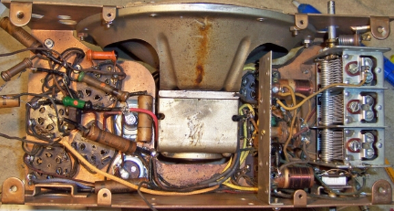
Servicing this radio is very difficult. Most components such as resistors and capacitors cannot easily be accessed. In order to begin my survey, I had to remove the power transformer, the 8-lug terminal board, the volume control assembly, tone control (rear chassis), tuning capacitor and the speaker! All three tuning capacitor mounting screws were hidden UNDER the antenna and first detector broadcast band coil shields! So these shields had to be removed for access to these screws, and then reattached to prevent damage to the coils. In addition, the screws retaining the antenna coil itself had to be removed and the coil moved aside in order to gain access to the tuning capacitor mounting screws! Access to several leads attached to the tuning capacitor was very difficult. The mounting screws had to be removed and the capacitor left in place and moved slightly in order to gain access to the bottom lugs with attached leads. Building this radio must have been quite a complex process! Most of the complexity was due to the very large speaker used, which took a lot of chassis real estate.
The tuning capacitor was cleaned in my old Heathkit Ultrasonic cleaner after removing the trimmer hardware and mica insulators. The capacitor was then cleaned using soap, water, and toothbrushes. The reduction drive assembly was also removed and cleaned. In order to return the trimmers to near their original positions, before removing the screws I note the original position of the screws (on the clock) and how many half-turns (and fractions) to completely tight. Once the cleaning and drying was completed, the trimmer hardware was reinstalled and the trimmer screws returned to where they were by fully tightening the screws then backing off the documented number of half-turns and fractions. I like to get them close to where they were originally before alignment.
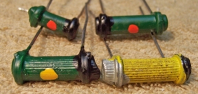
The original paper capacitors were restuffed using new axial film capacitors. They were a mix of Dubilier CUB and Sprague capacitors. Here is my Dubilier CUB capacitor restuffing process (see third type). The two Sprague capacitors were sealed with wax. Here is the restuffing process I use for those types.
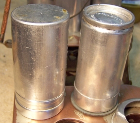
The two original filter capacitors had been removed in previous servicing. The schematic and evidence marks on the chassis indicated that they were originally 8mfd (voltage unknown) screw-based can type capacitors with single bottom lug terminals. Remnants of the original lugs were found in the extant wiring - the lugs had simply been cut off along with connected wiring, replacement tubular capacitors connected at that point, and the joint insulated with electrical tape. The input filter capacitor was originally insulated from the chassis. I found two similar dud screw based can type capacitors in my dud capacitor stock. These were both restuffed using 10mfd 450 volt electrolytics.
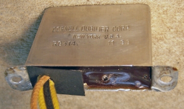
The original block capacitor was still in place. For some reason, a spring clamp had been clipped to the top of the capacitor and the handles of the clamp cut off! The capacitor was a metal cased rectangular unit containing five capacitors. Four were 0.1mfd and one was 0.2mfd. Three of the original leads had been cut and spliced. Perhaps the leads had been cut in order to test the capacitor during servicing? The splices had been insulated using electrical tape. The original contents were removed and the capacitor restuffed using 0.1mfd and 0.22mfd 630 volt film capacitors. New lead wires were installed. The original insulators were cleaned and reused. The case was sealed using rosin salvaged from servicing RCA Radiola Superhet catacombs, which melts at a low temperature and will not damage components.
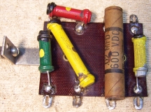
All resistors in the radio were older dogbone type resistors. Most were 1/2 watt size (a few were larger). Four resistors were out of tolerance by more than 20%. I maintain a stock of NOS and used dogbone resistors, and buy all I can find that are reasonably priced. I also NEVER throw away a used dogbone resistor, even if out of tolerance. Searching my stock, I found suitable replacements for all four (selected by measured value and size rather than marked value, since most resistors of this age will have drifted, even if NOS). Three were then repainted to the correct values using hobby enamel paint - one replacement (400K) was in tolerance. Here are the replacement resistors and the repaired terminal board (with a restuffed capacitor and repainted 500K and NOS 400K replacement resistors):
 |
 |
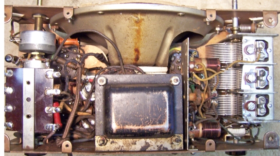
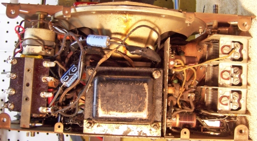
Seen below is the chassis after all capacitors have been restuffed and any out of tolerance resistors replaced. The speaker and tuning capacitor have been reinstalled. The power transformer, tone control, volume control, and terminal board have not yet been installed. One end of several parts have been reconnected. These connection points would be difficult or impossible to reach once additional large parts are installed.
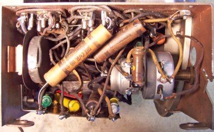
Below, the power transformer has been reconnected, but not yet bolted to the chassis. The primary leads have not yet been connected (awaiting installation of the volume control and line cord):
![]()
As found, the dial scale was not attached to the tuning shaft or the knob. It rotates behind the escutcheon plate, which has the pointer to the scale. It was not obvious how the scale originally was attached to the shaft or knob. But there was some markings on the scale that indicated that the scale was originally attached to the back of the tuning knob! This meant that the escutcheon had to be removed from the cabinet before the knobs and dial scale could be removed from the tuning shaft and the chassis removed. Failure to remove the escutcheon first would have likely pulled the scale free from the knob. The dial scale was secured to the back of the knob using glue. The knob and attached dial scale were then reattached to the tuning shaft and the escutcheon reattached to the cabinet. The dial scale was aligned with the dial pointer on the escutcheon so that the marking was close to the station being received.
The cabinet was vacuumed and then cleaned using GoJo (the white type, not pumice) hand cleaner and 00 steel wool. The escutcheons were not cleaned in order to maintain their patina. The tone control escutcheon on the back cover had obviously become lose at some point and was reattached very messily with glue, and slightly off center! There was really no way to repair it without destroying it. So it was left as is.
Three escutcheon screws were missing. The originals were very small #0 x 1/2" steel round head screws. I had brass hardware in stock that size. These had darkened and tarnished with age so they were presentable as is..
Once the radio was reassembled and the tubes installed, power was brought up slowly using a variac. A DVM monitored the B+. The radio came alive immediately and worked, which is amazing considering all the hacking and wiring errors discovered. The only problem found was that I had omitted one of the fiber washers which insulated the tone control bushing from the chassis. This resulted in the center wiper of the tone control being shorted to the chassis, since the bushing was "hot". As the tone control was adjusted, the audio to the 85 tube grid would be shorted to chassis in one direction, and the grid bias to the audio tubes reduced in the opposite direction.
The radio was then aligned. The IF frequency was 175kHz. One caution: the IF alignment trimmer screws are HOT with B+, so one must be careful not to touch the screwdriver shaft or to short them to the chassis! Only the broadcast band RF trimmers can be aligned. There are no trimmers for the short wave (police) band. Once installed in its cabinet, the tuning dial was set so that 1300kHz on the dial was correct. The tracking on the center and low end of the dial was not that good, but there was really no way to adjust tracking short of bending tuning capacitor plates.
The radio proved to be quite sensitive since it has a tuned RF amplifier on the broadcast band. The police or short wave band also worked well. The tone was excellent due to the large dynamic speaker. The tone control had very limited range even though it was original and tested good. The rebuilt volume and power control worked well even though the resistance was not as specified in the schematic. The AVC voltage was quite high on strong stations. It is not known if it was correct since the value of the volume control tap is not specified. The B+ voltage was correct as documented with 115 volts AC input.
Most of my restoration objectives were met, but not all. There was no intention of restoring the set to factory new appearance! My objective is usually to reverse any prior servicing and make the radio appear to have never been repaired. Here are some of my "misses":