Sparton Model 67 Restoration
My
antique radio restoration logs
There was no model number or any other information located anywhere on
the radio. The radio was identified by looking through Riders manuals for
Sparton radios with the same tube complement - there were several
possibilities. The model number was then identified by comparing the part
number of the speaker in the radio with the one specified in Riders parts list
for the model 67. Riders also had a chassis photo which exactly matched my
radio. Still, I cannot be sure that my radio is a Sparton model 67 or is another Sparton with the same chassis.
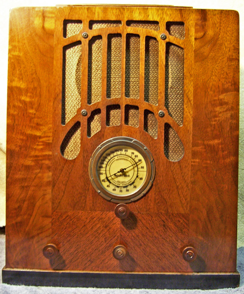 |
The 1934 Sparton model 67 is a conventional 6-tube
superhet that receives the
broadcast band and one short wave band The short wave band is
calibrated in METERS rather than megahertz - very unusual. The
radio has a tuned RF amplifier and uses 6.3 volt standard base tubes, typical of the early
1930's. The build quality is quite high.
The radio had seen extensive servicing in the past, with many original
components replaced. However I
decided to try and restore the original top and bottom chassis appearance as
much as possible.
The schematic and parts list for the radio can be found on Nostalgia
Air. |
Survey
My usual restoration procedure is to first make a complete
survey of the condition of all components. The survey results guide my
restoration strategy. If major and unique components are defective and
cannot be restored or replaced, I may elect to sell the radio rather than restore it.
When beginning a restoration project I assume that all paper and electrolytic capacitors are leaky and thus should be
replaced (I always "restuff" the original components if possible).
And I assume that most original resistors would have drifted and be out of tolerance range.
-
A type 85 tube had been installed to replace a 75 (not a
good replacement). The 6A7 tube was slightly weak. The remaining
tubes were all good. All were either RCA or Cunningham brand, and
likely the originals except for the 85.
-
The original can type filter capacitor block had been
removed and replaced by a dual tubular filter sticking through the original
filter chassis mounting hole! (fair enough - there is VERY little room under
the chassis).
-
Seven of the original paper-wax capacitors had been
replaced. Most of the original remaining Aerovox parts were mounted
with clamps riveted to the chassis. Some empty chassis rivet holes indicated
that many of the removed capacitors also had been mounted in this
fashion. Most replacement parts were not even close to the correct
values, and there were also some connection errors found later.
-
The power transformer was OK (very low wattage at no load,
and balanced high voltage windings).
-
The speaker field coil was OPEN, but the output transformer and
speaker cone were OK.
-
All RF coils and IF transformers were OK.
-
The original power cord and plug was usable.
-
The power switch on the volume control was defective but likely
only needed
cleaning.
-
Eight original resistors were out of tolerance
by 30-100%. One flexible wire wound unit was burned.
-
The speaker leads were cracked and frayed, and had been cut,
spliced back together, and taped. All the remaining wiring in the
radio was OK.
-
The dial drive shaft was bent and also frozen. The
speed reduction mechanism did not work.
-
Three knobs were missing - one original remained
(fortunately for matching purposes).
-
The dial cover glass had been replaced by a convex piece
marked Pyrex (and was the wrong size).
-
The tuning capacitor rubber grommets had deteriorated.
Cleaning
I normally clean the chassis before starting restoration.
I first blew off the above and below chassis dust with an air compressor.
The chassis was then partially disassembled for access and cleaning. The
tuning capacitor and dial drive mechanism was removed as a unit after
unsoldering the signal leads and ground braids. All the non-original
capacitors were then removed for access and restoration.
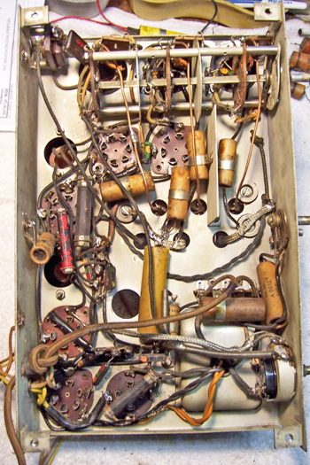
 |
Here is the chassis with all non-original parts
removed. |
The chassis and top components were then cleaned using GoJo, steel wool, and
various brushes. The tuning capacitor was removed and then was cleaned with soap,
water, and toothbrushes and then dried using a heat gun and then lubricated.
Repairs
Speaker Field
Before doing any repairs or investing $$$ in any missing knobs, I had to determine if
the speaker field, which was open, could be repaired or if the speaker could be
replaced by a suitable PM type speaker. Fortunately, the construction of the speaker was such that the
field coil assembly was attached to the speaker basket using bolts and thus was removable. The field
coil connections to the speaker's terminal board were removed, the cover
unbolted, and the cover and speaker field removed.
The news was not good. About 1/4 of one side of the field coil bobbin was burned
away, and the winding exposed. I carefully removed the burned and charred cardboard. It appeared that what happened was that the insulation on the wire
leading to the inside of the field coil had failed, and that the
wire had arced to hot end of the field coil. This burned away part
of the coil bobbin. A short stub of the winding remained sticking out of
the inside (start) of the coil. Unbelievably, there was continuity between
this wire and the outside of the coil!
I was able to splice a new lead (fine magnet wire) to this stub, insulate it using electrical
tape, and reattach it to the original wire lead. I then cut a new piece of
fiber to replace the damaged outside of the coil. The field coil was then
reassembled. It measured about 900 ohms (the schematic said 1600 ohms).
The remaining problem was centering the cone, since the field pole piece had
been removed to gain access to the field coil. If first tried using paper
shims between the voice coil and the pole piece. The retaining bolts were
then tightened. When the shims were removed, the voice coil was dragging
on the pole piece - it was not centered correctly. After several failed
attempts, I achieved success by slightly loosening the attachment bolts and then
striking the field coil housing with a plastic faced hammer to move it in a
direction away from the side where the voice coil was dragging.
Eventually, the voice coil was properly centered and did not drag. The
speaker was tested by attaching it to a field DC power supply and a radio before
proceeding with the repairs. It worked well and sounded good.
Paper Capacitors
The original Aerovox capacitors remaining were all restuffed. All
except two were originally installed using clamps. One clamp was soldered
to a terminal strip, but the rest were riveted to the chassis. The rivets
were drilled out, the capacitors restuffed, and the capacitors reinstalled using
screws and nuts. All capacitors had crimped ends rather than being sealed
with wax. One end of the crimp was cut off near the end with a razor blade
and the contents removed after heating with a heat gun. The cardboard
discs on each end were saved. On one end, the crimp remained so the
cardboard disc was reinstalled and the new replacement capacitor threaded
through the hole in that end. I used strips of paper towel wrapped around
the new capacitor to center and secure it inside the case. I then melted some rosin (discarded RCA
catacomb potting compound) and poured it into the opposite end. The
remaining cardboard disc was then slipped over the other end of the replacement
capacitor. It was held in place by the rosin (if rosin is not
available, one could use hot melt glue colored with hobby paint to reseal the
capacitors). In some cases the original leads were longer than those of the
replacement part. In this case, I spliced on new buss wire near the case
of the capacitor so that the splice was concealed inside the capacitor case
after resealing.
Main Filter Capacitor Replacement
The original filter capacitor (8+8mfd), a screw mount can type, was
missing. I replaced it with a similar screw mount can from my junk
box. I do not know if the original capacitor had terminal lugs or wire
leads. In any case, the replacement had wire leads. I cleaned out
the contents and restuffed this can using two 10mfd 450 volt electrolytics.
The common ground buss wire lead was passed through a hole in the base of the
capacitor, through the mounting hole, and soldered to a ground point on the
chassis. Most of this lead was hidden.
Resistor Replacement
There were two defective flexible wire wound resistors. For the type 42
audio output tube cathode bias resistor (500 ohms), I found a suitable
replacement in my junk box! The 6A7 cathode resistor was about 30%
high. Since I did not have a suitable replacement, I replaced this
resistor with a 1-watt carbon resistor inside the original
spaghetti tubing, which hid the modern component nicely.
There were six dogbone type resistors that were more than 20% out of
tolerance. These are replaced with dogbone type resistors as were
used originally. I picked out NOS and used dogbone resistors from my stock
and junk box that were close to the correct needed resistance (within +/- 20%) and then
repainted them to match the original resistor's color codes using hobby paint.
The replacements may continue to drift, as would most new carbon composition
type resistors. But to me, maintaining the original look is more important
than long term reliability of the radio.
The radio also used a third type of resistor that I have never seen
before. They are unmarked as to brand, and are about the same size as a
1/2 watt carbon composition resistor.
Since I had no practical way of reproducing these, and no replacement stock,
I decided to replace them with dogbone type resistors, since the radio also had
dogbone types installed.
Volume Control Repairs
The volume control was removed, disassembled, and the switch and resistance
element cleaned using "Big Bath" cleaner. The switch worked well
after cleaning, but later failed during testing. Sometimes the radio would
not turn off! So I had to replace the volume control.
Other Repairs
- The tuning drive mechanism was originally frozen and the knob shaft was
bend. The unit was removed from the radio, disassembled, and cleaned
using lacquer thinner and various brushes. I eventually was able to
free the shaft and bearing. I then carefully clamped the shaft in a
large vice and attempted to straighten the shaft. I was not able to
get it completely straight, but it did eventually work. Originally
there was a spring brass spacer washer between the two halves of the
unit. But when that was installed, there was too much slip and the
unit would not drive the tuning capacitor. I suppose this was due to
wear. After removing the spacer washer, the unit operated smoothly
(except for the small wobble in the knob staft!)
- David Frush (parts2many at AOL dot COM) was able to provide the three
missing wooden knobs
- The tuning capacitor rubber bushings were replaced using ordinary rubber
grommets. They worked, but of course were much stiffer than the
originals.
- A type 75 tube was installed in place of the incorrect type 85 tube.
A NOS type 6A7 tube was installed to replace the weak first detector
tube.
- The bandswitch was cleaned using Big Bath spray.
- The frayed and taped speaker leads were removed and replaced with new
wires.
- A new convex dial glass of the proper size was ordered from TimeSavers.com
Testing
After the radio was completely reassembled, power was applied through a
wattmeter and fused Variac. Power was brought up slowly while monitoring
the B+ voltage. Normal B+ was reached with only 100 volts applied, and the
radio worked. I assume that the high B+ was due to my using a 10mfd input
filter capacitor instead of the 8mfd originally used. At 110 volts AC
input, the B+ was 325 volts! At normal 120 volt (or higher) input, the B+
would be extremely excessive. I rechecked the power transformer voltages,
and the AC voltages were normal under load. I then remembered the field
coil problem - it measured only 900+ ohms, but the schematic called for 1600
ohms. So the field coil, although it worked, likely had some shorted
turns. After some experimentation, I installed a 1500 ohm 10 watt power
resistor in series with the field coil. This lowered the B+ to 325 volts
with 120 volts in, and the radio still worked well. I also installed a
CL90 surge suppressor in series with the AC line to reduce the cold starting
surge.
The radio was then aligned and all adjustments were already very close to
correct. It performs very well - it has excellent
sensitivity (due to the tuned RF stage) and good tone also.
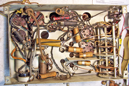
|
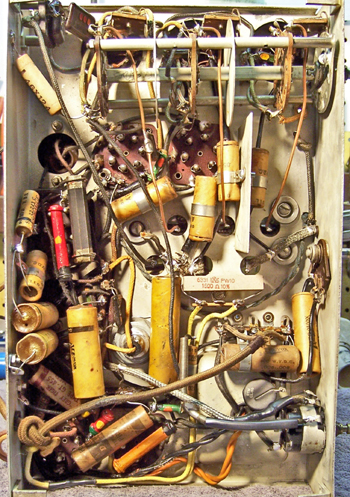
Chassis before restoration |
Chassis after restoration |
 |
 |
|
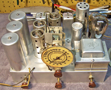
Restored Chassis |
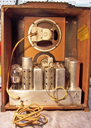
Cabinet Rear |
 |
 |