The schematic for the Stewart-Warner 3043 can be found on Nostalgia Air. Any part numbers will refer to numbers on that schematic.
|
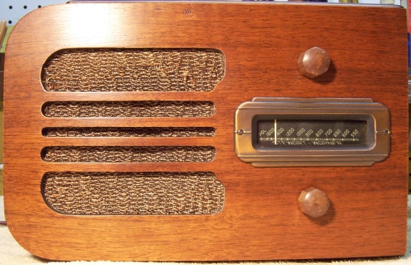
The Stewart-Warner Model 3043 from 1939 is a small five tube AC (transformer
type) table
radio. It receives only the broadcast band. The radio had seen
some servicing in the past, and what had been done was done
sloppily!. I decided to try to reverse any previous
repairs to the extent possible and to restore operation.
The schematic for the Stewart-Warner 3043 can be found on Nostalgia Air. Any part numbers will refer to numbers on that schematic. |
My antique radio restoration logs
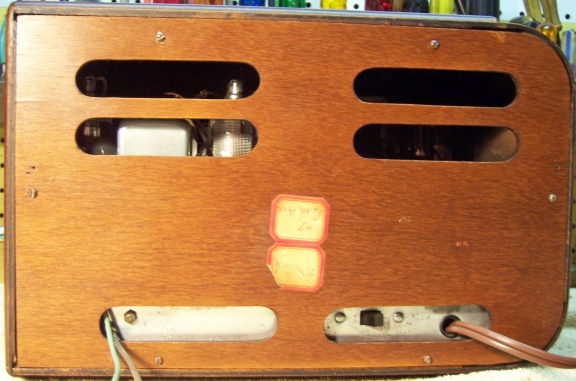
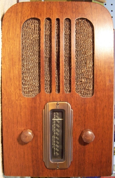
This radio was purchased on eBay. It was sold as not working. My example cabinet was presentable, with the usual scratches, wear and dings. It had all its original knobs and grille cloth, and the cloth was in good condition. The radio is quite unique in that it can be used either horizontally or vertically (like a small tombstone style radio) due to the angle of the dial scale lettering. The radio used all G type octal tubes. Stick on labels on the back perhaps indicated that an owner was "G. Newell, 47 Peck Ave." (city unknown, but this was sold from Cool, California).
The radio had seen some repairs in the past. It is not known if these repairs were done by service techs or by a collector.
All the tubes were branded Arcturus, all were all similar in appearance, and were likely original (four had date codes of D3, one had no date code).
The chassis mounted dual filter capacitor had been replaced by a clamp mounted Zenith branded capacitor on top of the chassis plus a tacked-in tubular capacitor under the chassis. This Zenith capacitor had likely been removed from another radio. It was a 3-section unit, but only one section was use. The remaining leads were clipped off.
The oscillator coil outer (tuned) winding had been sloppily rewound.
The output transformer had been replaced by a universal output transformer, which was not physically attached to the speaker. The primary leads had been spliced and insulated with electrical tape.
All original paper capacitors and dogbone type resistors were still in place.
The power cord had been replaced. A replacement was simply spliced onto the stub of the original power cord, and was not routed through the original chassis grommet. The replacement cord was not usable, so it had been there awhile.
My usual restoration procedure is to first make a complete survey of the condition of all components. The survey results guide my restoration strategy. If major and unique components are defective or missing and cannot be restored or replaced, I may elect to sell or keep the radio for parts rather than to restore it. I always assume that all paper and electrolytic capacitors are leaky and thus should be replaced (I always "restuff" the original containers if possible). Any mica capacitors are assumed OK until testing proves otherwise.
The power transformer was OK. The high voltage was balanced across the center tap with 20 volts applied through a variac. With full power applied (no tubes present), the wattage consumed was less than 10 watts. A transformer with shorted turns will draw excessive power and will heat up. I use a real analog watt meter for these tests. I always check for shorted turns before starting a restoration, since it may take some time before a transformer shows signs of overheating (after the owner has gone to the trouble and expense of replacing all capacitors or even investing in replacement tubes).
The antenna coil was OK.
The oscillator coil was open - both windings. The outer tuned winding previously had been rewound (scramble wound).
The IF transformers were OK.
The replacement output transformer was OK, but it was not attached to the speaker frame.
The speaker field coil was OK. The voice coil appeared to be rubbing the pole piece..
The AC switch on the volume control was not working. There were openings in the switch cover into which GC Big Bath cleaner could be sprayed. By doing so and cycling the switch, the switch started working.
The volume control measured about 440K (specification was 500K), but when rotated, the resistance jumped around, sometimes measuring open. Unfortunately this type of control cannot be cleaned using contact cleaner or GC Big Bath - the resistance element is simply a thin layer of carbon on a cardboard backer. Any attempts at cleaning will remove the thin carbon layer. I tried cleaning it, but the resistance then jumped to several megohms. The control would have to be replaced.
The tone switch on the rear chassis was broken
All the Arcturus branded tubes (likely all original) were good.
Incredibly, another chassis for this same radio appeared on eBay. It had been listed previously on eBay and not sold. I found it using Google while looking for other information on my radio. I was able to make an offer and purchase the chassis. I hoped that chassis would provide the parts I needed to restore my chassis. When received, I found:
The replacement chassis was in much better shape and than my original chassis. So this changed my restoration strategy for the radio. I would use the replacement chassis to restore the radio, since it was more original. I would substitute the tuner mechanism from the original chassis. The only roadblock to restoration of the radio that remained was the bad oscillator coil (in both chassis). I first removed the oscillator coil from the replacement chassis to check for any obvious break in the feedback winding. Nothing was found. I then decided to dissect the coil from the original chassis and determine its construction. At this point I would try to rewind the feedback winding. I would need to know the number of turns needed, perhaps the wire size, and winding direction. The construction appeared to be that the secondary winding was wound on a cardboard sleeve on top of the feedback winding. The non-original scramble wound secondary winding was removed and a heat gun used to melt some of the wax. The sleeve came off easily, exposing the feedback winding. I then noted the connections to the feedback winding and the winding direction and began to remove the winding while counting turns. There were several breaks in the winding, but I counted about 62 turns. At each point where there was a break, there was a green spot of corrosion. Using my micrometer, I found that the wire gauge used was about #36. I had a stock of #34 wire, so I then decided to attempt to rewind the feedback winding on the oscillator coil from the replacement chassis (which had a good secondary winding).
I disconnected the secondary winding on the coil from the replacement chassis and again used my heat gun to melt the wax retaining the outer winding and cardboard sleeve. The intact secondary coil and its sleeve came right off. The feedback winding was then removed, again confirming the number of turns and winding direction. The winding had many breaks, just like the coil in my original chassis. There were green spots of corrosion at each break. I rigged up a jig to hold the spool of wire and mounted the coil form in my small Unimat lathe. The drive belt of the lathe was removed and the pulley turned by hand. I wound about 60 turns of #34 wire onto the form in about the same place as the original winding. The cardboard sleeve with the good secondary coil was then reinstalled and retained by melting a small amount of the original wax using a small soldering iron. After reconnecting the windings to the terminals, both windings now measured OK. Hopefully I had wound the coil in the correct direction! This would have to be confirmed once restoration was complete.
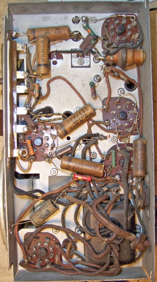
Since all showstoppers to restoration had now been resolved, I proceeded with the electronic restoration. All tubes were removed and dust was removed using an air compressor. Before starting repairs, I took photos of the original and replacement chassis top and bottom so that routing of wiring and component placement could be restored. Lead dress is often critical in radios.
When I replace a component, I always remove the original part completely from a terminal. Other components such as mica capacitors and in-tolerance resistors connected at the terminal are protected from heat using old medical clamps (hemostats). Excess solder is then removed using a solder sucker in order to expose terminal holes for reattachment of the rebuilt or replaced component.
Once components were removed for servicing, the chassis top, front, and back was cleaned using GoJo (white) hand cleaner and 00 steel wool. Since the steel wool may leave small fragments behind that could cause shorts, I go over the cleaned chassis with a vacuum cleaner and magnets.
The tuning unit was removed from the replacement chassis and also from the original chassis. The unit from the original chassis would be used, since the unit from the replacement chassis had been damaged in shipment. The tuning capacitor was also swapped, since the mounting holes for the dial and drive assembly were different on each chassis. The tuning capacitor was cleaned in my old Heathkit Ultrasonic cleaner after removing the trimmer hardware and mica insulators. The capacitor was then cleaned using soap, water, and toothbrushes. In order to return the trimmers to near their original positions, before removing the screws I noted the original position of the screws (on the clock) and how many half-turns (and fractions) to completely tight. Once the cleaning and drying was completed, the trimmer hardware was reinstalled and the trimmer screws returned to where they were by fully tightening the screws then backing off the documented number of half-turns and fractions. I like to get them close to where they were originally before alignment.
The antenna coils was also swapped, since the coil from the replacement chassis had lost some of its wax protective coating (and this way it would be used with its original tuning capacitor).
The original paper capacitors were restuffed using new axial film capacitors. Here is how I normally restuff paper capacitors. C9 (the metal clad line bypass capacitor) was removed from the original chassis and restuffed using a .015mfd/630 volt axial capacitor. This capacitor had been replaced in the second chassis, but was original in the first chassis. It was quite difficult to restuff this capacitor, since it was not sealed with wax, but rather had metal ends crimped over fiber washers. One end was drilled out, retaining the fiber washer on the opposite end. The contents were removed with difficulty using drills and needle nosed pliers. The capacitor was resealed using rosin salvaged from servicing RCA Radiola Superhet catacombs.
Capacitors C6 and C10 were later discovered to be replacements, since they were a different brand and their solder joints were not original. Their leads were just hooked around the terminals, and were not routed through terminal holes. Also, remnants of the original component leads were found on the terminals. These capacitors were vintage replacements. The corresponding capacitors in the original chassis were original Sprague capacitors, so these were removed, restuffed, and used to restore the second chassis. This meant that all paper capacitors in the second chassis were now branded Sprague.
The filter capacitor in the second chassis was original: a stud mounted cardboard cased unit rated 8+8mfd at 300 volts. It was restuffed using two 10mfd 450 volt axial electrolytics. The capacitor had a common positive lead with separate negative leads. The original capacitor was sealed with tar. Most of the tar was removed using a 1" spade bit in my drill press. The remainder of the contents were then pulled out using needle nosed pliers. The two replacement capacitors were wrapped in strips of paper towel to center them in the case, then sealed using hot glue. New wire leads were attached.
All resistors in the radio were older dogbone type resistors. All were 1/4 or 1/3 watt size. All were within 20% tolerance except for R21, the AVC resistor which was 25% high. It was decided to leave it in place, since it is not critical. The same resistor in the original chassis was ALSO out of tolerance so it could not be swapped.
One section of the Muter Candohm wire wound resistor measured 21% high. All sections of the original chassis Candohm measured OK, and I could have swapped the units. However it was riveted to the chassis. I tried my usual Candohm restoration procedure: squeezing the metal case near each terminal using a small C-clamp. This brought the out-of-tolerance section to +17% and all other sections much closer to specs. Since the Candohm insulation was still in good shape, and since all sections were now in tolerance and their resistance stable when the terminals were moved, I left the original in place. In this radio, the Candohm is a bias divider and is not carrying high voltages. If it should fail shorted or open, no serious damage will result.
All the Arcturus branded tubes from the original chassis were used. All tested good. The line cord and plug were replaced with a new vinyl cord which was about the same diameter as the original stub. The pilot lamp lead had been cut, spliced, and taped. I replaced it with the socket and lead from the original chassis, which was in good shape. The original chassis ground lead (black) was used. A new antenna lead was used, since the antenna leads on both chassis were in poor condition.
The cabinet was vacuumed and then cleaned using GoJo (the white type, not pumice) hand cleaner and 00 steel wool.
Once the radio was reassembled and the tubes installed, power was brought up slowly using a variac. A DVM monitored the B+. The radio came alive and worked immediately. It was then aligned, which was straightforward. The B+ (175 volts) measured 179 volts with 115 volts AC input. The radio seemed quite sensitive using my 30' indoor basement antenna, and we are in a rural area.
Most of my restoration objectives were met, but not all. There was no intention of restoring the set to factory new appearance! My objective is usually to reverse any prior servicing and make the radio appear to have never been repaired. The replacement chassis was restored and used, with the following parts taken from the ORIGINAL chassis:
The line cord was not usable on either chassis, so a new vinyl cord with molded plug was used. It was however the same wire size as the original. There was no visible evidence that the oscillator coil had been rewound. The (likely) non-original volume control on the replacement chassis was left in place, since it worked and the shaft type and length were correct.
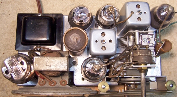
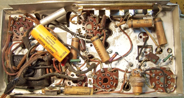
Replacement Chassis Before |
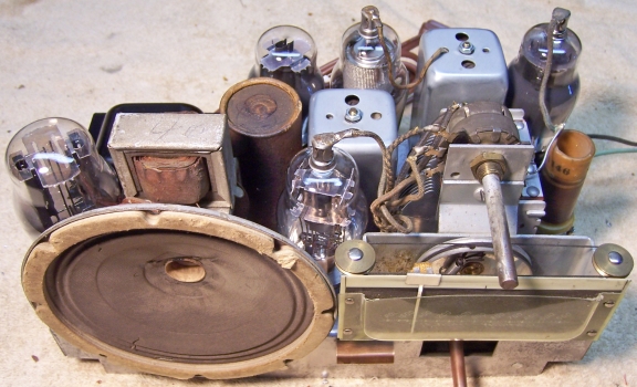
Replacement Chassis After |
 |
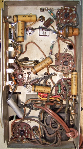 |
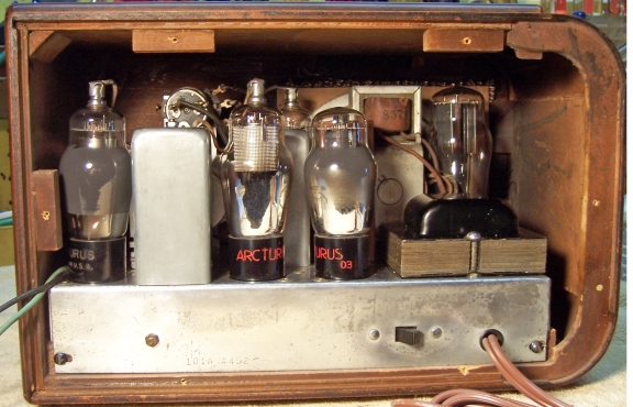
Original Chassis Before Restoration - The Parts Source |
 |