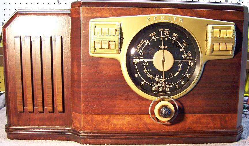
Zenith 10S531 (10-S-531) Restoration
|
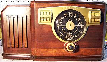
The Zenith model 10S531 (10-S-531) from 1941 is a large tabletop
10-tube AC superhet circuit radio with push-pull 6V6 output tubes. It is in reality a console size
chassis (Zenith deep chassis) in a very large table top cabinet. It receives the standard broadcast band and two short wave bands, has
"automatic" or push-button tuning, and the Zenith RadiOrgan
tone control system with six controls. The radio had seen minimal servicing in the past -
most of the original parts were still in place. I decided to try to reverse
all previous repairs to the extent
possible. I did have a 7S342 parts
set, just
in case a major part was bad!
The schematic for the Zenith 10S531 can be found on Nostalgia
Air. Any part numbers mentioned will refer to numbers on that schematic. |
My
antique radio restoration logs
Condition As Found
This radio was purchased at the 2011 Charlotte AWA Radio Conference in
the auction. It was obvious that the cabinet would need to be
refinished. Two holes had been drilled into the side of the cabinet,
and one hole had a toggle switch installed with
leads going to the speaker voice coil (apparently for a switched extension
speaker - the other hole was likely for a jack). I do not normally purchase radios that have been refinished or
that NEED to be refinished. But since this would be a keeper, and since we
have a very capable craftsman in town that can refinish cabinets, I decided to
bid on it, even though the cost of restoration and purchase would likely exceed
its value (and if sold, it would be VERY expensive to pack and ship)! The radio had its back cover, so I did not get an opportunity
to check out the chassis before the auction. Later I discovered that the chassis had quite a
bit of surface rust on the top. There was considerable corrosion on the dial bezel,
and one automatic tuning tab was broken. The tuning knob was warped, as
was the dial pointer center plastic disc.
Previous Repairs
-
Filter capacitor C17-C18 had been replaced by a similar
clamp mounted unit, with the same values.
-
Most of the tubes had been replaced. The 6K7G IF amplifier
had a metal 6K7 installed and the tube shield had been removed.
-
The wire lead to the 6F5G first audio amplifier had been
replaced (it had likely shorted to the shield).
-
Two wax-paper capacitors had been replaced (one of the C15's, and C4).
Survey
My usual restoration procedure is to first make a complete
survey of the condition of all components. The survey results guide my
restoration strategy. If major and unique components are defective or
missing and
cannot be restored or replaced, I may elect to sell the radio rather than restore it.
I always assume that all paper and electrolytic capacitors are leaky and thus should be
replaced (I always "restuff" the original containers if possible).
Any mica capacitors are assumed OK until testing proves otherwise.
-
The AC power switch was bad (it measured high resistance) - dirty and/or oxidized contacts
were likely.
-
The tuning shaft (hollow brass) was broken near the knob end and had been
soldered back together.
-
One tube shield was missing.
-
Zenith would originally install G type tubes with shields as
needed. Original tubes would have been branded Zenith. The original
Zenith 6A8G tube grid cap had broken off and was not repairable (broken flush
with the glass). The Zenith 6J5G phase
inverter was very weak. GT type tubes were installed for one of the 6V6G
output tubes as well as the 6X5G rectifiers. The other 6V6G was very
weak. A metal 6K7 had been installed for the IF amplifier. The
remainder of the tubes were good.
-
One chassis suspension spring was missing.
-
The antenna terminal A-Z link was missing (almost always is!)
-
The tuning capacitor grommets were bad - typical of the age.
-
The wave trap L10 was open. All other RF coils and the IF transformers were OK.
-
The speaker field and cone was OK.
-
The output transformer had an open primary (1/2 of it).
-
The power transformer checked out OK (this radio uses two 6X5 rectifiers,
but has a separate filament winding for the rectifiers which eliminates the
risk of a heater-cathode short frying the power transformer).
-
The power cord looked original and in good condition, but the AC plug was
broken (it could have been a vintage replacement - don't know).
-
The speaker plug was broken, and two of the pins were not attached to the
plug.
-
The Wavemagnet antenna plug was missing - only the pins remained (the plug is thin
fiber and easily broken).
-
Two original dogbone type resistors were out of tolerance.
-
Two wax-paper capacitors had been replaced (one of the C15's, and C4).
-
The Candohm metal clad resistor R19 was fortunately good.
-
Almost all wiring in the radio was rubber covered and the insulation was
falling off. Almost all wiring would have to be replaced.
Repairs
The back cover was removed, and then the radio was removed from its
cabinet. Since the RadiOrgan tone control panel will not pass through the
hole in the dial bezel, the switch mechanism had to be removed from its frame first
(one screw plus a ground lug) and then passed through the hole in the
bezel. I did not want to cut the cable, even though it would have to be
replaced (I wanted to keep the cable intact until its leads could be measured
for replacements). The dial bezel was then removed, which provided access to the
screws holding the automatic tuning unit to the cabinet. The automatic
tuning unit was then unplugged and removed, followed by the chassis and speaker.
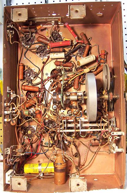
At this point I made BEFORE photos of the chassis top and bottom, as well as
the cabinet. I use these photos to ensure that replacement parts and
wiring are placed as close as possible to their original positions. Some
radios are subject to problems (such as oscillation) if wiring is re-routed or
lead dress is not the same as the original..
All tubes and tube shields were removed. The dial pointer was removed. The
dial scale and attached band change
mechanism, volume control shaft, tuning shaft, flywheel and tuning
intermediate pulley were removed for access to
components below and for cleaning and lubrication. The tuning capacitor was removed for
cleaning and replacement of chassis grommets. All non-original parts were then removed.
The top and sides of the chassis was cleaned with GoJo hand cleaner and 00 steel
wool. Since this process may leave small steel wool fragments that can cause
problems later, I follow up with a thorough vacuuming and go over everything
with a small magnet and masking tape to pick up any stray fragments.
Almost all of the failed rubber covered wiring in the radio was then replaced
using non-rated cloth covered wire (both solid and stranded). The same
color was used as the original, except that there is no gray color available.
I use the smaller diameter wire available from Radio
Daze. Their larger diameter 600 volt rated wire (and the only type now
available at Antique Electronic Supply)
is totally inappropriate for radio restoration. I feel the non-rated wire
is at least as safe as the original wire in the radio! Only a few buried
wires in the RF section were left, for fear of damaging a coil attempting to
replace them. Most of these were very short and there was minimal risk of
a short. As the wiring was replaced, any terminals that also held
components that would eventually have to be replaced (resistors or capacitors)
were left unsoldered at this point. I continue to this day to use the old
Heathkit convention for soldering (or unsoldering!) a terminal: for example,
(S-2) means Solder 2 leads, (NS) means No Solder (at this time).
I as able to purchase a replacement wave trap (L10), automatic tuning tab
assembly, the missing chassis suspension spring and antenna plug from Tom Myers on
Antique Radio Forums. The tuning shaft had apparently broken at the outer
slot (knob end) at the groove where the retaining C-clip would be attached. The shaft had been soldered
together. Unfortunately, this solder blob prevented removal of the shaft
for cleaning and lubrication. The solder blob was removed. I decided to try
to adapt the tuning shaft from my 7S342 parts chassis. It was in good
condition, but slightly SHORTER than the one in the 10S531. After a trial
fit, it was determined that there was enough length to hold the tuning
knob. But I had to cut a new slot for the outer C-clip. That was
done using my Unimat lathe and squared up using a small file. I also used the
7S342 drive pulley rather than the original pulley, which was designed for a
flat belt rather than the round O-ring I planned to use. All the volume, band switching, and tuning parts
were cleaned and lubricated prior to re-installation. The tuning drive
belt was replaced using a large O-ring which was cut at 45 degrees and joined
using super glue. The tuning worked smoothly and correctly.
The dial pointer plastic disc was warped badly. This was repaired by
first removing the metal dial pointer, which is held to the plastic disc by bent-over tabs. The plastic disc was then placed on a flat piece of MDF with a
hole to clear the hub on the back. A few seconds with a heat gun then
pressing evenly while it cooled greatly improved the situation. The metal
dial pointer was then reattached.
The tuning capacitor grommets were replaced by modern 5/16" rubber
(vinyl) grommets.
The tuning capacitor was cleaned in an ultrasonic cleaner followed by soap,
water, and toothbrushes. The bearings were then lubricated using distributor
cam lubricant (which is similar to the original grease used). Before
cleaning, the trimmer micas were removed in order to prevent damage. In
order to get the trimmers back to approximately where they were originally set,
I first note the position of the trimmer screw on the clock, then count the half
turns (and fractions) from that position to fully tight. The micas and
trimmer hardware were also cleaned in the ultrasonic cleaner and then dried
before reassembly. After reassembly, each trimmer is again turned to fully
tight position, then backed off the appropriate number of half turns and
fractions. This process will return the trimmers to close to their
original positions (later fixed by a full alignment).
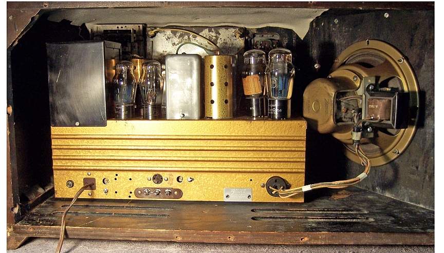
The output transformer on the speaker was replaced using a Stancor A-3852 universal push-pull transformer rated at 18 watts. The voice
coil was measured as 3.4 ohms DC resistance, and thus I estimated the impedance
as 4 ohms. The appropriate transformer
secondary taps were then selected to match as closely as possible push-pull 6V6 tubes to the
4 ohm voice coil
(using the instruction sheet that came with the transformer). The closest
available ratio was 10000 ohms to 3.38
ohms. The mounting
holes in the transformer bracket were slightly enlarged to accommodate the
replacement transformer. A suitable speaker plug was attached to replace
the broken plug - it was found in my junk connector stock. The replacement looked similar to the original (black
bakelite), but had 5 pins instead of 4 (only 4 are used - the socket on the
chassis has 5 pins so that the 5-pin plug could be used without having to cut
off the extra pin). Once the restoration was complete and during
installation of the chassis into the cabinet, I found out that the larger output
transformer interfered with the loop antenna! So I had to rotate the
speaker clockwise one hole in order to provide clearance.
The power switch on the volume control was flooded with Big Bath cleaner/degreaser
through a small opening in the control. After the switch was cycled many
times, it worked well.
Resistors and Capacitors
All original Zenith paper capacitors were rebuilt in their original cases
using modern 630 volt axial film capacitors in order to maintain the original
under-chassis appearance. I reseal the original cardboard tubes using rosin
salvaged from RCA catacombs (it melts at a low temperature and will not damage
the replacement capacitors). I collect original Zenith (as well as Philco
and other branded type) wax/paper capacitors for use when the originals are
missing or have been replaced. Zenith schematics in Riders Manuals indicate the Zenith part
numbers of the capacitors used. I was able to find the correct part
numbers for the two missing original Zenith capacitors in my stocks or the 7S432
parts chassis. They were then restuffed and sealed.
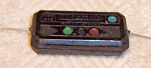
The line bypass capacitor C19 was a Micamold 0.005mfd/600 volt capacitor.
These capacitors may look like mica capacitors, but are instead normal wax/paper
capacitors. This one was very leaky - not good! I was able to slice
it open using a hobby razor saw, remove the contents, enlarge the inside using a
Dremel tool, insert a 0.0047mfd/630 volt film capacitor, and cement the halves
back together using epoxy.
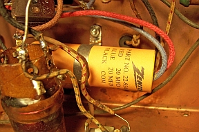
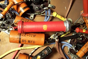
The original Zenith filter capacitor C17-C18 (20+20mfd at 450+350 volts) had
been replaced by a newer clamp mounted unit with the same values. I
restuffed the replacement capacitor using two 22mfd 450 volt units, attached new
wire leads, and sealed the case using melted rosin. I created a
reproduction label for this capacitor using Microsoft Word. The label verbiage
used on the label was copied from an original Zenith filter in my parts bin (which was
also a dual unit but not
clamp mounted). Remnants of the rivet that held the original capacitor
were found on the chassis, and the replacement attached at that point using a screw (the
remnants of the rivet
was drilled out). While I do not know exactly what the original Zenith
filter actually looks like, my copy is likely closer than a generic replacement.
Both out-of-tolerance resistors were replaced by the same type dogbone resistors.
One was R22, a 22K 2 watt dogbone resistor. I collect NOS and used dogbone
resistors just for this purpose. I found a NOS 20K 2 watt dogbone in my
stock that measured almost exactly 22K. It was repainted using hobby paint
as a 22K 10% resistor, just like the original. The other bad resistor was
R2, a 100K 1/4 watt dogbone. I found a NOS dogbone resistor in my stocks
that was within 10% tolerance. All I had to do was to paint the end silver
to indicate 10% tolerance.
Tubes
Correct G type tubes were installed for the two 6X5G's, two 6V6G's, 6K7G and
the 6J5G phase inverter. The original weak 6J5G phase inverter was
installed as the detector. An original Zenith gold 1941 tube shield was installed for
the 6K7G IF amplifier.
Cabinet
The original automatic tuning unit had one broken tab and was in poor
condition. I was able to
obtain a replacement panel as well as other parts needed from Tom Myers on
Antique Radio Forums. Here is the original unit (left) and the
replacement.
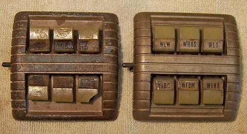
The station selector tabs are retained by a long shaft that is held by
soft metal projections on the back. Usually these projections will break if disturbed (the
casting is likely some sort of pot metal). The latch push button assembly was
first removed - it is held to the casting by a screw. The shaft holding
the tabs was then freed from the retaining metal projections and carefully routed out of
the casting through the hole in the side of the casting made vacant by removing
the latch push button mechanism. The plastic tabs could then be removed. The
tabs were cleaned in an ultrasonic cleaner. The casting was stripped, wire
brushed, and then painted using Rustoleum Aged Brass spray paint. The
tabs, shaft, and latch button were then reinstalled. A dab of epoxy was
used to secure the shaft, since some of the original retainers were broken
during removal. This same process was used to refinish the RadiOrgan tone
control panel.
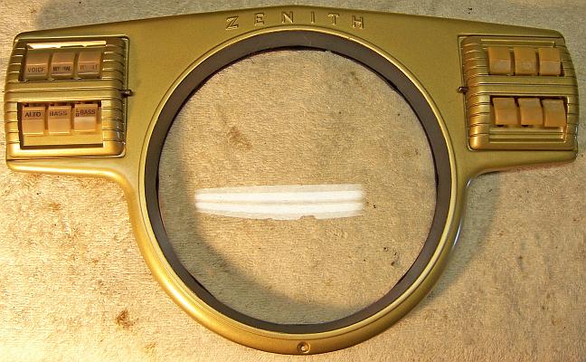
I purchased a replacement tuning knob for the radio while at the Charlotte
AWA Radio Conference. The original Zenith volume knob was warped also, but I
found a better example in my knob stock. The dial glass rubber extrusion
(U Channel) was hardened and falling apart. It was replaced by a
reproduction available from Alan
Jesperson and Radio
Daze. The dial bezel was stripped
and repainted using Rustoleum Aged Brass spray paint. The cabinet was
refinished and the two holes plugged by a local craftsman.
Repainted Bezel and Control Panels
Testing and Alignment
Once the radio chassis was reassembled and the tubes installed, power was brought up
slowly using a variac. AC power consumption was monitored using a watt meter, and a
DVM monitored the B+. The radio powered up and the audio section worked,
but there was no reception. Recall that the Wavemagnet antenna plug was
originally missing, and the pins were simply plugged into the antenna
socket. I was not sure if the connections were correct. I decided to
determine the correct connections before attaching the replacement plug.
After some investigation, I swapped two leads and was able to received a station
strongly. However, the same station was received all across the
dial! It was later determined that the radio was GROSSLY out of alignment,
and especially the IF transformers. Once the IFs were adjusted correctly
at 455kHz, the radio worked well. At this point, I went through a complete
alignment procedure.
Once the radio was working correctly and aligned, the replacement Wavemagnet
antenna plug was attached. When I picked up the replacement plug, I did a
WELL DUH! The replacement plug had remnants of the Wavemagnet wires still
attached! That would have told me which wire went where, and saved a lot
of time. The automatic tuning unit was cleaned up and
lubricated, and the push buttons were
adjusted to local stations.
The radio performs well, and has very good tone, but has excessive bass if the LO
BASS tone button is pulled. The speaker cone excursion was excessive to
the point of distortion and possible damage on stations with lots of bass
(classic rock or classis country stations - my only choice locally other than
talk or sports). I originally suspected the replacement
output transformer, since it was much larger than the original (more iron, thus
more bass response). After consulting the good people on
Antique Radio Forums, a common opinion was that this is normal in many
cases, since today's stations have a lot more bass than when the radio was
new. I did experiment some with the tone control capacitors, but any
change I made to capacitor values made matters worse. So I decided to
leave the radio as is and to not use the LO BASS boost button.
Restoration Results
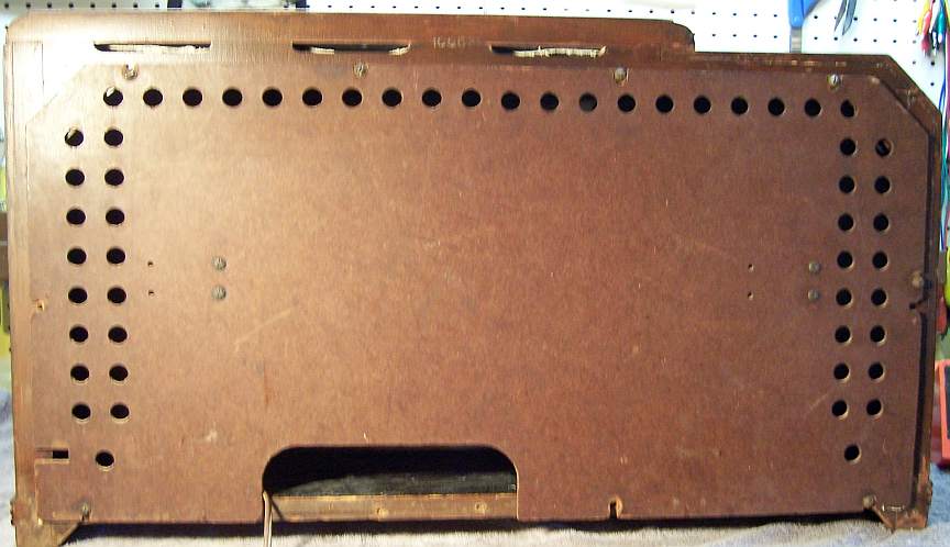
Chassis Bottom Before and After Restoration
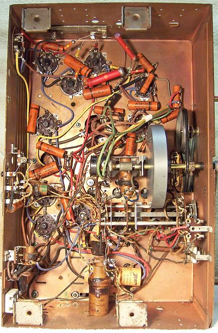
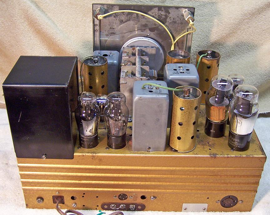
Top Of Chassis Before Restoration
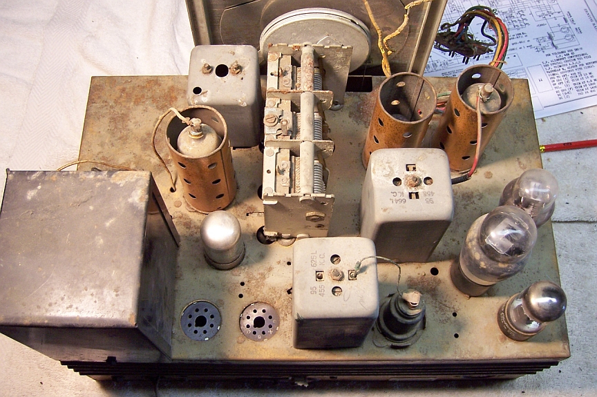
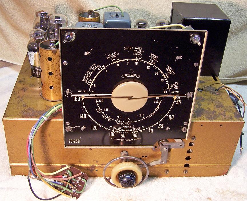
Top Of Chassis After Restoration
Completed Restoration - Cabinet Refinished