Zenith 4V31 (4-V-31) Farm Radio Restoration
 |
The Zenith 4V31 is a 6 volt DC farm radio, used in rural
areas before electrification. These radios were typically operated
from 6 volt storage batteries charged by Zenith Windchargers (wind turbine
powered generator), motor generator sets, or simply the farm tractor!
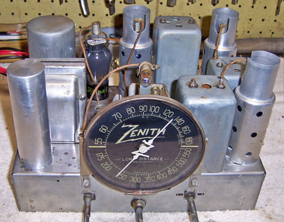
The
circuit is conventional: a 4-tube superheterodyne that receives only the
broadcast band. It uses a mixture of 2 volt (rare type 15) and 6
volt tubes.
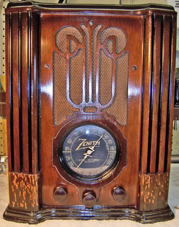
The cabinet was in excellent condition, although likely at least
partially refinished, and the grille cloth was
OK. The knobs were original. There was some deterioration of
the photo finish area at the bottom of the cabinet. But the radio
still displays very well.
The radio had seen some servicing in the past but had not been hacked excessively.
Later on I found evidence that the radio had been restored. However
it was sold as "untested". This being the case, I
decided to try to restore the original top and bottom chassis appearance if
possible.
The schematic for the radio can be found on Nostalgia
Air. Any part numbers will refer to the numbers on that schematic. |
My
antique radio restoration logs
Survey
My usual restoration procedure is to first make a complete
survey of the condition of all components. The survey results guide my
restoration strategy. If major and unique components are defective and
cannot be restored, I may elect to sell the radio rather than restore it.
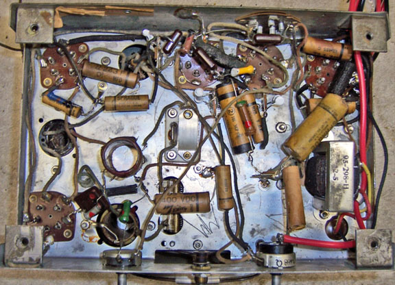
I assume that all paper and electrolytic capacitors are leaky and thus should be
replaced (I always "restuff" the original containers if possible).
-
The filter capacitor had been restuffed (the restorer had
used 47uf capacitors vs. the 2 and 8uf specified)
-
The filter choke (Part 10) had been replaced, and was hanging in mid air by one
screw. A terminal strip was added for connections to the filter capacitor leads (the original choke had lugs)
-
None of the paper caps had been replaced or restuffed
-
One of the buffer capacitors (Part 15) had been replaced with a 0.01uf 600 volt mylar
(it should have been 1000 volts). The actual radio used TWO 0.01uf
capacitors rather than one (from each side of the high voltage secondary to
ground).
-
It appeared that the vibrator had been operated on.
There were signs that it had been re-sealed with caulk. Later on it was found that it
worked, but was VERY noisy.
-
The original 6 volt power leads had been removed. A thin wire was attached to supply 6 volts (probably for testing).
-
Four original "dogbone" resistors had drifted from 30-100% and needed to be replaced.
-
All coils and transformers were OK
-
The speaker was OK
-
The antenna lead label was missing (ground lead label was
present)
-
The original chassis washers were still supple and usable -
RARE!
-
All tubes were good
-
The cathode bias for the 75 1st audio tube was developed differently than shown on the schematic. The schematic shows a 1K
resistor to +6 volts and a 250 ohm resistor to ground. In the actual set, there was a 100K resistor to B+ and a 1K resistor
to ground.
-
The tone control circuit was different. The schematic showed a 50K pot in series with a 0.03uf capacitor across the
speaker (there is no output transformer in this radio - it uses a high impedance magnetic speaker). The radio, AS WELL AS
A PARTS SET, had a 5.4K resistor instead of a capacitor in series with the tone control pot. I do not understand how this
could work. But I left it in place.
Repairs
I had a rusty 4-V-31 parts set that had a severely water-damaged cabinet
available for a parts set in case something was needed such as a coil or
transformer.
All paper capacitors were rebuilt in their original cases
using modern 630 volt film capacitors in order to maintain the original
under-chassis appearance. The replacement mylar buffer capacitor was
removed and replaced with a proper Zenith paper-wax capacitor that was restuffed
using a modern ASC X-675 type 2000 volt film capacitor (the remaining buffer
capacitor was also restuffed).
Filter Choke (Part 10). I could not live with the replacement
that had been installed if there was any other choice. I had nothing better in my junk box.
The parts set had an original choke, but it was open. Play Things of Past did not list the choke as in stock. I carefully removed the frame
and laminations, preserving the "gap" material. I removed the outer coil insulation to examine the connections to the
terminals. There was no problem with the soldered connections, so I went deeper. I exposed the outside windings and began
to unwind the fine wire, hoping to find a break. I encountered several breaks in the first layer, but still no continuity.
So I went on to the second layer. About 2/3 through the second layer, continuity was established. I then reassembled the
choke and installed the repaired coil in its laminations. Chokes have an air gap to prevent saturation. It is important
that this gap be maintained during reassembly. The gap in this case was formed by a thin piece of fish paper or waxed paper. This was preserved as well as possible and reinstalled between the E and I section of the core.
Filter Capacitor. The 47uf capacitors currently installed inside the original can were much too large. The original was only 2uf + 8uf at 250
volts. The restuffed capacitor had been sealed with caulk. I removed the caulk and installed more appropriate capacitors:
4uf and 10uf (at 450 volts).
There were three 990K resistors and one 490K resistor that needed to be replaced. I found some dogbone resistors in my junk box
and NOS dogbone stock that had drifted to close to 990K. I repainted them using enamel purchased from a hobby store. Most
were originally in the 500K range. I assume that the resistors took 60+ years to drift by 100%, so future drift would not be excessive
(at least in my lifetime). To me, maintaining the original look is
more important than long term reliability of the radio.
The chassis and top components were cleaned using GoJo, steel wool, and
toothbrushes. The tuning capacitor was removed and cleaned with soap,
water, and toothbrushes and then dried using a heat gun and lubricated.
Testing
After completion of restoration, the radio was connected to my 6 volt power
source. The radio came alive immediately and worked, but the vibrator was
extremely noisy (it apparently had been opened and repaired in a previous
"restoration"). I tried the vibrator from my parts set, but it
was dead. I was able to rejuvenate it by connecting the interrupter
circuit to 120 volts AC in series with a 60 watt lamp. Once the interrupter
began working, the vibrator was installed in the radio and after awhile worked very
well. I find that if you can get a NOS vibrator to start "buzzing"
it will clean its own contacts if operated for awhile under load. Even a
NOS vibrator will likely not work initially due to outgassing of the foam
insulation inside which coats the contact surfaces. The
replacement vibrator was very quiet.
B+ was very close to specifications at 6.17 volts DC input. There was
some RFI from the vibrator, probably due to worn contacts. I'm not sure
how much of this "noise" is normal for this radio. The radio
worked very well after alignment. As previously noted, the tone control circuit was
different from the schematic, and there was some doubt if it would work. Testing showed that it worked very well, and in fact
it worked better than if a 0.03uf capacitor were used instead of the 5.4K
resistor. I still do not understand how this could work.