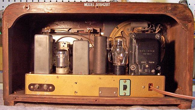
Zenith 5S642BT (5-S-642BT) Restoration
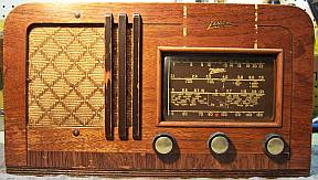 |
The Zenith 5S642BT (chassis 5B10BT) from 1942 is a 5-tube AC Superhet
circuit radio that
receives the broadcast band and three short wave bands. The 5S642BT is a
Zenith export model built in the USA but capable to operating on either
115 or 225 volts, 50-60 Hz. The radio appeared to be all original, with
all original parts still in place - even the original Zenith OEM
tubes! Only the power cord with attached plug had been replaced so
the radio could be used (it was used in Chile). Since the radio was
original, I decided to attempt to restore the radio and maintain the original chassis appearance if
possible.
I was unable to find a schematic or any service information on this
radio on-line. However the circuit is virtually identical to the Zenith
model 5S042BT, chassis 5C63 except that my radio does NOT have a
phonograph connection and some tube types are different (6K6G vs GT etc.) The schematic for the Zenith 5S042BT can be found
in Riders Volume 15 Zenith page 21. There is an entry for 5-S-42BT on Nostalgia
Air, but the actual schematic has not been loaded - only the clarified
schematics, chassis layout, and service information. Any parts references
in this document will refer to
the Riders/RadioMuseum schematic. That schematic can be viewed at Radio
Museum, but membership is required for access.
|
My
antique radio restoration logs
Overview
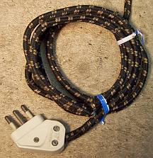
The radio was purchased on eBay and was sold as "not
tested". The
power cord with attached plug was identified as the type used in Italy, Chile
and Uruguay using an excellent article found in Wikipedia on mains plugs
and sockets used worldwide .
The plug was marked as made in Chile. The eBay seller later confirmed that indeed this
radio had been used in Chile. It had been inherited and had been in storage for
30 years. The fact that the plug could not be used in the USA likely saved the
radio from damage due to plugging it in "to see if it worked".
Previous Servicing
It is indeed rare to find a radio that is all original. The only part that I
could find that had been changed was the power cord and plug. The dial drive
cord had been repaired, but was original - a break had been repaired by splicing
in another piece of cord. Even the tubes were original Zenith OEM! Date codes
were 2W, 1M, Y1 and Y2 (1941 or 1942?). None of the tubes had an "R" indicating a
Zenith replacement. All tubes except the 6K6G were weak or bad. It is likely that
the radio would have been used until it quit working, since parts would have
been difficult to obtain during WWII and especially in Chile!
Cleaning
The chassis was very dusty, but not rusty. All tubes, were removed.
The dial mechanism was removed for cleaning access and to replace the dial cord.
The dust was vacuumed
and blown off with an air compressor, top and bottom. The top and sides of the
chassis was cleaned using using old tooth brushes and a vacuum to removed dust
from the crevices, followed by GoJo (white) hand cleaner and 000 steel wool. The
steel wool was kept well away from the tube sockets and tuning capacitor. The
chassis was again vacuumed in order to catch any steel wool fragments.
Survey
In Zenith schematics, all
resistors and capacitors having the same part number have the same schematic
reference call
out. So for example, there may be multiple R2's or C4's on the schematic.
Before I start work on the chassis I annotate the schematic so that all parts
have unique identifiers. I usually add an alphabetic suffix, so that the
part numbers are thus R1A, R1B, etc. I then annotate the schematic and under-chassis photo with
these unique part numbers using a red pen.
-
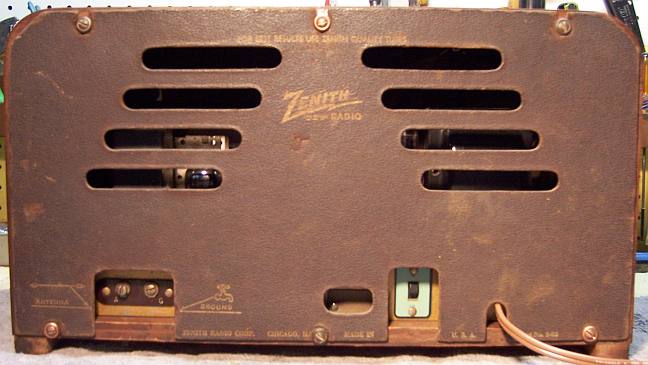
The cabinet was in poor condition with extensive finish
loss. The knobs were original, and even the knob felts were present. The
back cover was present and in good condition.
-
The dial lamps were OK.
-
The line cord was OK but not the factory original.
-
The tuning capacitor mounting grommets were OK, which is
fortunate, since the screws retaining them are underneath the complex band
switch wiring.
-
The dial drive cord had been repaired, but the knot
sometimes caused the tuning shaft to bind up.
-
The speaker field, cone, and output transformer were OK.
-
The power transformer was OK. The high voltage winding was
balanced across the center tap with 20 volts AC applied through a Variac, and the wattage was
less than 10 watts at full line voltage (no tubes).
-
All coils and the IF transformers were OK.
-
The radio used some rubber covered wiring, all of which was bad.
If a wire were moved even a small amount, the insulation would fall off.
Most of this wiring would have to be replaced. Fortunately all of the
signal level RF and band switch wiring was cloth covered and OK.
-
Only one resistor (R5, 10K 2 watt) was out of
tolerance.
-
The AC switch was bad, but did respond to a shot of GC Big
Bath spray cleaner followed by repeated operation.
-
The 6K6G tube was OK. The 6X5GT/G indicated a short. The
6SQ7GT and 7Q7 were very weak. The 7A7 was slightly weak.
Restoration Strategy
Since the radio was all original and the chassis was in
excellent condition, I
debated about restoring it at all! Replacing all of the rubber covered wiring
is difficult and is prone to error. But I feared that if the capacitors and
wiring were not replaced, future capacitor failures or shorts could easily
destroy the radio. I have found that the majority of eBay radio sellers
will plug in the radio "to test it" if physically possible.
Experienced radio sellers often cut off the power cord if the radio is being
sold as needing restoration, untested, or for parts, since it may pass through
many hands over many years before someone attempts to test or restore it.
In this case the Chilean power plug likely saved it, plus the eBay seller
inherited the radio directly from his/her grandfather and no collectors or
dealers were involved. The cord would be replaced with a
new brown vinyl cord with molded plug, somewhat similar to the likely original
type.
I assume that all paper and electrolytic capacitors are leaky and thus should be
replaced (I always "restuff" the original components if possible). I
do not replace mica capacitors, but may test them in place if possible (usually
this requires disconnecting one end of the capacitor).
Since all of the original parts were still in place I decided to maintain the
original chassis appearance to the extent possible. Normally I would
rebuild all original wax-paper capacitors as well as the filter capacitors in
their original cases (restuff them). The out of tolerance resistor R5 (a 10K ohm
2 watt 20% old style carbon composition
type) would have to be replaced. Unfortunately any original replacement would
likely also be out of tolerance, so another type of replacement would have to be
used..
When I replace a component, I
always remove the original part completely from a terminal. Other good components connected at the terminal are protected from heat using old medical
clamps (hemostats). Excess solder is then removed using a solder sucker in order to
expose terminal holes for reattachment of the rebuilt or replaced component.
Repairs
Rubber Covered Wiring
All of the crumbling rubber covered wiring would have to be
replaced. The insulation would fall off if the wire was even slightly
moved. Fortunately the RF section signal level wiring was all cloth covered and
was OK. Most of the existing wiring was about #24 solid in various
colors. To replace it, I used #20 cloth covered hookup wire (unrated
voltage),
available from Radio Daze
and possibly other suppliers. Their 600 volt rated wire is not suitable for
radio restoration - it is MUCH too large. One particular Zenith color (slate),
is not available. In this case I used black. Another color (a grayish green) was
replaced using green. One difficulty in using the #20 wire
is that the conductor diameter is much larger than the original wire used. This
makes it difficult, or in some cases impossible, to thread multiple leads
through some component lug holes - and especially loctal tube socket lugs (which
I hate). I did manage to replace all filament and B+ leads,
as well as most signal level leads. I have not found a source for #24
solid wire with cloth covering - only plastic/PVC etc.
The wiring to the second IF transformer was also rubber covered and
had to be replaced. This required removing the transformer from the
chassis. The wire colors on the schematic did not match the colors used on the
transformer. So I decided to use the colors specified on the 5S042BT schematic
(for slate, I used black).
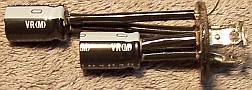
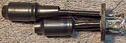
Wax/Paper Capacitors
All of the original Zenith cardboard tube type capacitors were
restuffed using modern 630 volt axial film capacitors. Unfortunately two of the
original capacitors were branded Zenith but made by Solar (Seald-Tite - part number
suffix "AM"). These are a solid
body of wax with a thin paper wrapper and cannot be restuffed! So I
decided to replace these capacitors with the more usual Zenith parts made with cardboard tubes
sealed on each end with wax. These can be restuffed and then resealed. I collect branded (Zenith, Philco, Sprague,
RCA/GE etc.) dud capacitors just for this case, and for cases where an original
part has been replaced by a modern part. The part number suffix (not shown in
the schematic) varies with the supplier. For example, a Solar branded part may
be coded 22-819AM, vs. a Sprague supplied part with the same value may be coded
22-819E.
In cases where I did not have the correct
Zenith part number which corresponded to the Solar provided part, I used a
Zenith part with the same capacitance and voltage rating. For C5
(22-818AM, .05/400v) I used a 22-828C (.05/400v). For C23 (22-1063AM .001/600v)
I used a 22-887F (.001/600v). For C25, the output tube plate capacitor
(0.004mfd/1000v), I used two 0.01mfd/630 volt capacitors in series. These
would just fit inside the original case when placed end to end.
My re-stuffing process is as follows:
- The original capacitor is removed from the radio, and the required lead
length and any insulating sleeving use noted.
- The low melting point wax from each end of the original (or replacement)
capacitor is melted and removed using an old
25 watt soldering iron.
- The original wire leads are removed, as well as any remaining wax.
- While the internal wax is still molten, a small screwdriver is used to push out the
original paper-foil roll. In some cases, the contents came out when the leads
were pulled out.
- The original cases are then cleaned out, and any wax and dirt on the
outside removed by gently heating the body with a heat gun and
wiping with a paper towel while still molten.
- If the required lead length is longer than that of the replacement
capacitor, a piece of buss wire is attached before restuffing. The splice is
made close to the capacitor body so that the splice is hidden inside the
cardboard tube after re-sealing.
- The replacement capacitor is wrapped in a narrow strip of
paper towel in order to keep the new capacitor centered and to keep it from falling out.
- The finished capacitor is then sealed with melted rosin (salvaged from
early RCA Superhet catacombs, and donated by or purchased from members on Antique
Radio Forums).
- I do NOT recoat the outside of the rebuilt
capacitors with wax (I'm not sure what was originally used - probably
beeswax). The original capacitors had a VERY thick covering of this
wax, plus embedded dirt. Once removed, the capacitors appeared
yellow. Most Zenith capacitors of this vintage appear orange colored.
I suppose it depends on the parts supplier.
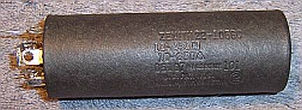
Filter Capacitor
The original filter capacitor C28/C29 was removed from the chassis for
restuffing.
It was a twist lock type capacitor rated at 10mfd/450 and 10mfd/350 volts with a
cardboard cover. But it was not the usual type of twist lock capacitor, in that both
sections had individual positive and negative connections, rather than a common
negative connection. The positive lead of C29 (10/450) went to the bottom
terminal marked with a square. The negative lead went to the metal
can. The positive lead of C28 (10/350) went to the bottom terminal marked with a
triangle. The negative lead went to the unmarked bottom
terminal. The capacitor was restuffed using two 10mfd 450 volt radial lead capacitors. My
procedure for restuffing twist lock type can capacitors is as follows (there are many
discussions and examples with photos using slightly different techniques on Antique
Radio Forums):
- Remove the cardboard cover. In this case, I had to use a heat gun to
soften the tar
holding it to the can. Sometimes the cover will pull off easily without
heating. It is important not to pull using the capacitor's terminals,
but rather the ground tabs, while the heated cover is held using an old wash
towel or rag.
- Clean the outside of the metal can using lacquer
thinner.
- Remove any excess tar from the inside of the cardboard cover using
mechanical means (small screwdriver).
- Uncrimp the bottom of the metal can using a small screwdriver and small diagonal cutters (try to
minimize damage to the outside of the can)
- Remove the mounting ring, the top terminal board, the gasket material and
another circular fiber board,
cutting the aluminum leads to the capacitor body to free up the terminal assembly. I
had to peel back a small area of the can in order to be able to insert a
small screwdriver under the terminal board and start the removal process.
One must be VERY careful and not break the terminal board, and to keep the
terminals attached to both fiber boards (do not allow the terminals to
pull free of either board).
- Remove the sticky sealing material between the two terminal boards using
needle nose pliers, screwdrivers, or whatever is needed.
- Clean both parts of the terminal board assembly using lacquer thinner and
old toothbrushes. This is done so that the two parts can be glued
together.
- Glue the two parts of the terminal board assembly using epoxy secured by
clamps.
- Remove the can contents using a heat gun to release the tar, followed by a
thorough cleaning. I first remove as much tar and other crud using mechanical
means. Next the can is filled with mineral spirits and allowed to soak
overnight. The dirty solvent is discarded and the can cleaned using clean
mineral spirits and an old tooth brush.
- Connect the replacement capacitor leads to the original terminals by
drilling small holes through the terminal board close to the terminals,
passing a lead through the holes, and soldering them to the terminals on the
inner side of the lug. I use small numbered drill bits and a Dremel tool -
the drill bit used is only slightly larger than the component leads to be
used.
- The common ground lead of C29 is passed through a small hole drilled near
one of the capacitor ground/mounting tabs. This lead is not soldered
to the ground lug until after the capacitor is secured in the chassis
mounting wafer (otherwise the solder would prevent the lug easily passing
through the hole in the mounting wafer or could damage the wafer - ASK ME
HOW I KNOW THAT).
- Reinstall the terminal board and mounting ring and restore the crimp
around the base (I use a plastic faced hammer).
- Reinstall the cardboard cover (it was not glued - just held by friction).
The cover hides any signs of the bottom crimp being disturbed.
Resistor R5
Resistor R5, a 10K 10% 2 watt old style carbon composition
resistor was 30% out of tolerance. I attempted to reproduce it by drilling
a hole in another similar resistor large enough to insert two 4.7K 1 watt
resistors in series. The similar resistor was held in my Unimat
lathe. But this did not work - I as unable to drill the hole without
damaging the resistor. Another alternative would be to install a modern
10K 2 watt resistor. But this would really be out of place. So
instead I used a 2 (or 3) watt old style dogbone resistor I had in stock that
was in tolerance for 10K ohms. It was originally marked as 6.8K but now
measured 9.5K. So I repainted it as a 10K 10% resistor using hobby enamel
paints. I collect old style dogbone resistors just for this purpose.
Many Zenith radios, even post war models, used old style dogbone
resistors. So this type of resistor would not be out of place in 1942.
Tubes
The bad 6X5GT/G was replaced by a 6X5G, which originally would
have been used (the tube socket is so labeled). The weak 7Q7 and 6SQ7GT tubes were replaced. The 7A7 (slightly
weak) and 6K6G (good) were
left in place. Unfortunately I could not find Zenith branded tubes. However, the
original bad Zenith OEM tubes will be kept with the radio and not discarded.
Other Repairs
The line cord was replaced using a new brown vinyl cord and plug. The dial
drive cord was replaced using a similar type material. This was a difficult
procedure since the cord goes through two holes in the chassis and twice around
the tuning knob shaft, access to which is partially blocked by band switch and
RF wiring. The cord was replaced before the dial assembly was
reinstalled. The original spring was re-used.
Testing and Alignment
Once the radio had been reassembled,
the radio was powered up using a fused Variac. The radio came alive and
actually worked on all bands. The set was then aligned. I did not touch
the short wave oscillator trimmers - only the antenna coil trimmers (if
used). The short wave bands worked very well as is, and my signal
generator does not go higher than 10mHz. The radio is quite sensitive and has
very good tone. The only tone control is a treble cut switch on the rear
chassis.
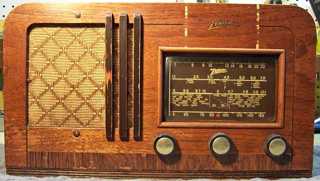
Cabinet
The cabinet was vacuumed then carefully cleaned using GoJo (white) and cleaner and 000
steel wool. The finish was very fragile and had heavy wear and finish loss. I
then went over the cabinet using Howard's followed by a coat of Johnsons Wax.
Restoration Results
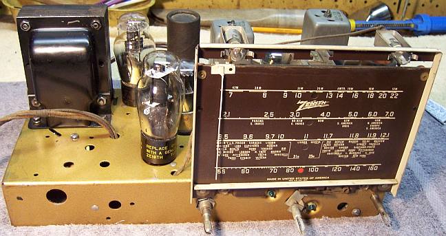
Chassis Before Restoration
|
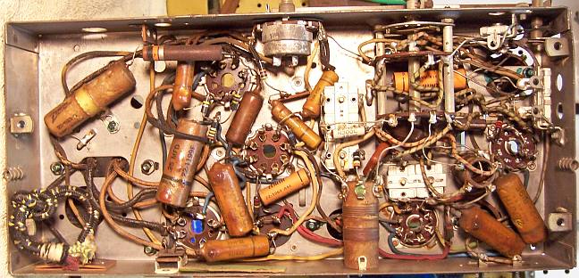 |
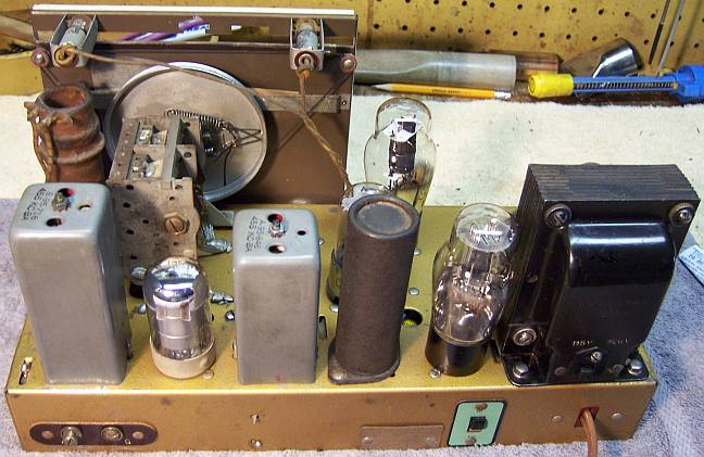
Chassis After Restoration
|
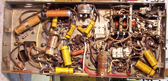 |