Zenith Model 7S633 (7-S-633) Restoration
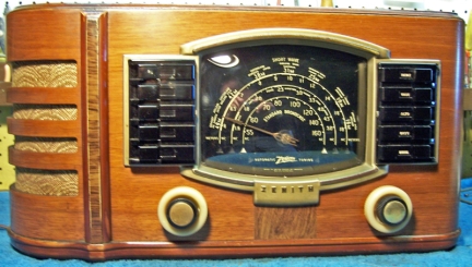 |
The Zenith model 7S633 (7-S-633) (1942 model year) is a tabletop
7-tube AC superhet circuit radio.
It receives the standard broadcast band and two short wave bands, and has
"automatic" or push-button tuning. This example had seen extensive
servicing in the past. I
decided to try and restore the original top and bottom chassis appearance if
possible and reverse previous repairs to the extent
possible. I was not 100% successful in restoring the radio to its
original condition - some compromises had to be made.
The schematic for the Zenith 7-S-633 can be found on Nostalgia
Air. Any part numbers will refer to numbers on that schematic. |
My
antique radio restoration logs
Previous Repairs
-
As found, the radio actually worked.
-
The power transformer had been replaced by a much oversize
unit. In order to reduce the B+ voltage, a 3K 10 watt resistor had
been installed between the 6X5 cathode and the first filter capacitor and
speaker field. The failure of the previous transformer may have been
due to an internal 6X5 short, or perhaps leaky bypass or coupling
capacitors. The original filter capacitors were still in place and
still OK (the radio worked). There was signs of tar leakage from the
old transformer, so the failure was likely slow and due to overheating
rather than catastrophic.
-
All the tubes were likely replacements, and some were
incorrect types. A 6X5GT was installed (should be 6X5G), a 6AC5GT output tube was installed (should be
6AC5G), and a 6P5GT was installed (should be 6P5G). All the replacement tubes tested
good.
-
Resistors R1 and R2 (52 and 33 ohms) had been replaced by a
single 8 ohm wirewound resistor, thus disabling the change in RF bias when
in short wave mode.
-
R10 (27K 1 watt) had been replaced by a 2 watt wirewound
type
-
One pilot lamp was a #47 (should be #44)
-
Several bypass and coupling capacitors had been replaced
(C3, C15, C16, C20, C21, C22), mostly in the audio section.
Survey
My usual restoration procedure is to first make a complete
survey of the condition of all components. The survey results guide my
restoration strategy. If major and unique components are defective or
missing and
cannot be restored or replaced, I may elect to sell the radio rather than restore it.
I always assume that all paper and electrolytic capacitors are leaky and thus should be
replaced (I always "restuff" the original containers if possible).
Any mica capacitors are assumed OK until testing proves otherwise.
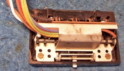
The
automatic tuning unit (push button assembly) was first disconnected in order to
prevent damage to the fragile coils during handling the chassis. Fortunately, only four wires had to be
disconnected. I found:
-
The AC power switch on the volume control was bad - dirty and/or oxidized contacts likely.
-
The speaker field, output transformer, power transformer, and all RF and IF
coils and transformers were good. However, the power transformer was
NOT ORIGINAL.
-
The tuning capacitor mounting grommets were bad.
-
Lots of rubber covered wire was bad - the insulation would crumble and fall
off if the wire was moved even a slight amount. Most of this wiring
would have to be replaced.
-
The back cover was missing (reproductions available)
-
The volume control knob was missing its brass insert (replacements
available)
-
The 7A7 IF amplifier tube was slightly weak (1200/1750)
-
Several resistors had drifted and were now out of tolerance (R13,
R15). R1, R2, and R10 had been replaced by incorrect types or values.
-
The loop antenna primary coil L1 was open.
-
Tuning capacitor grommets were bad.
-
The power cord was OK (rubber or vinyl). I'm not sure it was original.
Repairs
I decided I could not live with the replacement power transformer.
Fortunately, I had a junker 7S529 radio in stock (which was damaged in shipment).
Its power transformer was good, and was the correct type and physical
size. Comparing the 7S529 and 7S633, the B+ voltages were very close, and
the AC filament current slightly higher in the 7S529. So I decided to
remove the transformer from the 7S529 and use it for the restoration of the
7S633. Since there was some rust on the transformer, I wire brushed it and
then repainted it with black satin lacquer.
I first removed all the non-original components, documenting their locations
and connections. The volume control was removed for access. The tone
control panel was disconnected (its wiring would have to be replaced anyway).
All tubes and shields were removed. The tuning capacitor was then
removed for cleaning access to the chassis, and to replace the mounting grommets
(I used standard rubber grommets). I then took photos of the chassis
bottom so that routing of wiring and component placement could be restored.
Lead dress is often critical in radios. When I replace a component, I
always remove the original part completely from a terminal. Other
components connected at the terminal are protected from heat using old medical
clamps. Excess solder is then removed using a solder sucker in order to
expose terminal holes for reattachment of the rebuilt or replaced component.
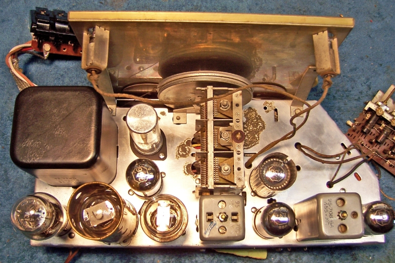
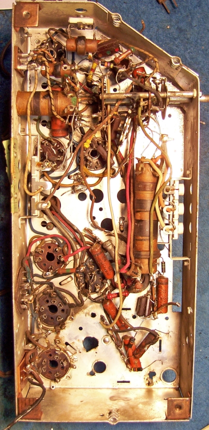
At this point, the chassis looked like this:
The top of the chassis was cleaned with GoJo hand cleaner and 00 steel
wool. The tuning capacitor was cleaned in an old Heathkit ultrasonic
cleaner with dilute ammonia. After drying, the bearings were lubed with
Lithium grease.
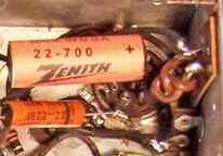
Resistors and Capacitors
All the original Zenith paper capacitors were rebuilt in their original cases
using modern 630 volt film capacitors in order to maintain the original
under-chassis appearance. I reseal the cardboard tubes using rosin
salvaged from RCA catacombs (it melts at a low temperature and will not damage
the replacement capacitors. Since several original Zenith capacitors had
been replaced, I searched my stock of old Zenith parts for the correct part
numbers. In most cases I found the correct original part and restuffed it
with modern 630 volt film capacitors. Capacitor C15 (Zenith part #22-854,
500pf, 600 volts) was a problem. There was not room inside the original
capacitor shell for a silver mica or ceramic capacitor. So it was
restuffed using two 0.001mfd/630 volt film capacitors in series. In
one case, I did not have the original Zenith part in stock (22-1119, .005mf,
1000 volts). So I used a Zenith 22-229F shell (.005mf, 600 volts) and
restuffed it with a 0.0047mfd 630 volt film capacitor (this was C21, the line
bypass capacitor). There was not room to restuff using a correct Y-type
safety capacitor.
Many of the components that had to be replaced were buried beneath the
bandswitch. These were VERY difficult to get to without damaging other
parts, but I managed.
R1 (52 ohms wirewound, 1/2 watt) was replaced using a 51.6 ohm flexible
wirewound resistor. R2 (33 ohms 1/4 watt) was replaced by a 33 ohm 1/2
watt carbon resistor. Since these parts were missing, I had no clue as to
what the originals looked like.
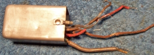
While the original filter capacitor C17-18-19 (15+5mfd @ 450 volts and 15mfd
@ 350 volts) was OK (the radio worked), I could not trust it since it was likely
leaky and could fail at any time. Unfortunately, there was not enough room
inside the original can for the three replacement capacitors required. So
I restuffed it with 2 22mfd @450 volt capacitors used as C18 and C19. C17
would have to be external. The original can was restuffed using the
following technique:
- The crimp around the base was uncrimped
- The fiber terminal board and fiber backer were removed after the aluminum
connecting the terminals to the body of the capacitor were pulled from the
terminals.
- The old contents were removed by applying a heat gun to melt the tar which
retained it.
- The old can was cleaned out.
- The fiber backer was epoxied to the underside of the terminal board in
order to retain the original terminals.
- Holes were drilled through the fiber backer and terminal board close to
the terminals.
- The new components were installed inside the old can. Leads for the
common ground and two positive leads were routed through the drilled holes
and attached to the original terminals.
- The terminal board was reinstalled and the crimp on the base restored.
A separate 22mfd @ 630 volt capacitor used as C17 was disguised by
fabricating a Zenith type cover (a Zenith part number was made up, but the value
on the cover reflected the value of the replacement capacitor inside).
The one dogbone resistor out of tolerance was replaced by a NOS dogbone
resistor that had drifted to near the correct value. It was repainted
using hobby paint to the correct color codes. While this resistor may
continue to drift, so will the others in the set. I wished to maintain the
original above and below chassis appearance.
Wiring
Most of the original rubber covered wiring had to be replaced. The
insulation would crumble and fall off if the wiring was moved even the slightest
amount. The cable to the tone control panel had to be replaced, as well as
the wiring to the Second (output) IF transformer:
 |
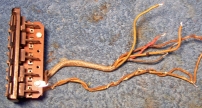 |
| Second IF transformer Wiring |
Tone Control Panel Wiring |
 |
| Rewired Tone Control Panel |
Wiring to the pilot lamp sockets as well as most all the B+ wiring and some
filament wiring was replaced. Any wiring that did not have to be
disturbed, was left alone.
Tubes
A new 6X5G tube was installed to replace the existing 6X5GT. A NOS 6P5G
was ordered to replace the 6P5GT (a quite pricy tube!). I had a 6AC5G tube
in stock which tested 700/1000, so it was used. The 7A7 tube was slightly
weak and was replaced. The remainder of the tubes were good.
Other Repairs
The volume control switch was flooded with Big Bath cleaner and cycled many
times. The switch eventually worked. The push-button tuning contacts
were also cleaned using Big Bath followed by lacquer thinner on Q-tips.
The loop antenna primary coil L1 was repaired. This required that the loop
be disassembled without disturbing the loop winding.
A reproduction back cover was ordered from RetroTronics.
A replacement volume control knob was ordered from Great
Northern Antique Radios. Alan did not have a reproduction knob in
stock at the time, but was able to supply an original!
Testing and Alignment
Once the radio was reassembled and the tubes installed, power was brought up
slowly using a variac. AC power consumption was monitored using a watt meter, and a
DVM monitored the B+. The radio came alive immediately and worked,
although it was not very sensitive on the low end of the broadcast band.
The replacement transformer worked fine, but the B+ was a little high.
This was likely due to using larger input filter capacitors (22mfd vs 15mfd) or
a slightly weak 6AC5 output tube (measured 700/1000). So I normally
operate this radio (and most others in my collection) using my 110 volt stepdown
transformer (line voltage here is 123 volts!)
The set was then aligned - no surprises. Several adjustments were
way off - especially the BC band low-frequency tracking capacitor. The push buttons were
adjusted to local stations without difficulty.
The set worked well on all bands, and the Tone Organ tone control operated
correctly. The only problem I had was some modulation hum and distortion
on a couple of stations. I researched the topic of tunable hum or
modulation hum on the Antique Radio Forums.
It was found that the problem could be eliminated by simply moving the radio
away from power lines near my work bench! The Wave Magnet antenna in this
set is not shielded.
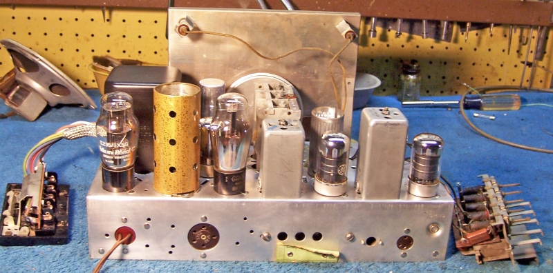
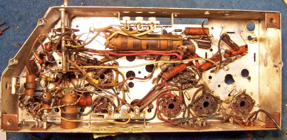
Restoration Results
|
Chassis Before Restoration |
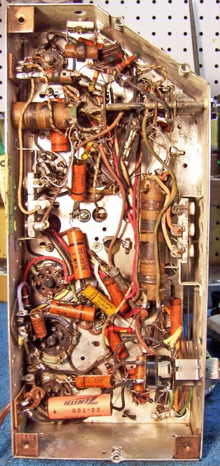
Chassis After Restoration |
 |
 |