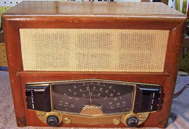
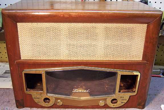
Zenith 8H032 (8-H-032) Restoration
|
The Zenith 8H032 from 1946 is an 8-tube AC Superhet that
receives the broadcast band, the old FM (FM45) and new FM (FM100)
bands. This radio would have been used during the transition to the
new FM band (88-108mhz) starting in 1945. The old FM band is no
longer used for broadcast radio. The schematic for the 8H032 can be found on-line at
Nostalgia
Air. For this restoration I had an original SAMs Photofact,
which is fortunate since the Nostalgia Air schematic is very difficult to
read.
The radio had seen major servicing in the past. Many paper
capacitors, the filter capacitor, and perhaps all the tubes had been
replaced. I decided to try to reverse these repairs and to restore the
set to its original condition to the extent possible, yet get it working. |
My
antique radio restoration logs
Condition As Found
This radio was purchased on the shopgoodwill.com
auction site. This site combines items from many different Goodwill stores
under a common auction site structure with search, auction style bidding and
checkout capability. The radio appeared complete and in good condition,
but was stated as not working. The knobs, bezel, dial cover, back cover, and grille cloth
were all present and apparently in good condition. The listing noted some alligatoring and other
finish defects. Unfortunately, the radio was not packed very
well, and was delivered by UPS (not a good combination). The radio was in
pieces when received. Previous experience with UPS claims has shown that
UPS will not honor an insurance claim if the item is not packed sufficiently
and/or there is no visible damage to the carton.
So I decided to request a refund (fortunately available from
this particular Goodwill store). I sent them photos of the damage, and
they refunded my debit card the full amount including shipping and handling
costs in a couple of days. They did
not request the radio (in pieces) back, but did later file a damage claim with
UPS (which UPS likely paid, since this was only a $40 radio). So since the radio was basically
free, I decided to at least attempt restoration IF the cabinet could be
repaired. Otherwise, I would keep it as a possible future parts set when I
find a better example.
Previous Repairs
-
All tubes had likely been replaced at some point. None
were Zenith branded. The 5Y3GT had been replaced by a 5Y3G.
-
Seven wax-paper capacitors had been replaced (the usual
suspects: the audio coupling capacitors, the limiter screen bypass, the line
bypass capacitor, and several tone control capacitors including the
output tube plate capacitor). Some were in very difficult-to-replace
locations, so likely someone paid a lot of money to have this radio
serviced.
-
There were several Sprague capacitors without Zenith part numbers. I
assumed that these were replacement, but I was not sure. I have seen
many Zeniths with Sprague capacitors, but these all had Zenith part numbers.
-
The LO BASS tone capacitor (.005mfd) had been replaced with
a .001mfd unit. I'm not sure why, unless this was an attempt to reduce
excessive bass (which does happen with modern radio stations).
-
The three-section filter capacitor had been replaced.
-
One resistor had possibly been replaced by a modern 1 watt
type - unlikely due to a failure (tone circuit) - perhaps it was damaged
when a paper capacitor sharing a terminal was replaced!
-
There was tape on the FM line cord antenna lead and on the 6S8GT grid cap
lead because of failed insulation on the rubber covered wiring.
-
The line cord plug had been replaced - the line cord was
original but not usable.
-
The grille cloth was secured to the cabinet using large tacks. It would
have originally been secured by staples, which may have pulled loose when
someone pushed on the grille cloth.
-
The dial bezel had been secured by two round head screws at
the bottom, and two 4-penny NAILS at the top (bent over
behind). The screws were larger than the originals would have been and
were the wrong type. Perhaps the screw holes in the cabinet were damaged and would no
longer hold the original screws.
-
The speaker cone surround had been coated with some paint-like
substance, and cotton had been stuffed between the cone and speaker basket
on the back. I have no clue what this was supposed to
accomplish. There was no obvious damage to the speaker cone, and
testing showed that the speaker worked (although I was not sure what it
would sound like in the completed radio). Perhaps there was a rattle.
-
The back cover had breaks near the bottom and had been
patched back together using tape.
-
The dial cord had been replaced.
-
The pilot lamps had been replaced with the incorrect types.
Survey
My usual restoration procedure is to first make a complete
survey of the condition of all components. The survey results guide my
restoration strategy. I never apply power to a radio before
restoration, even through a "dim bulb tester" or variac "to see
if it works". If major and unique components are defective or
missing and
cannot be restored or replaced, I may elect to sell the radio for parts rather than restore it.
I always assume that all paper and electrolytic capacitors are leaky and thus should be
replaced (I always "restuff" the original containers if possible).
Any mica capacitors are assumed OK until testing proves otherwise.
-
The line cord looked original, but the plug had been replaced. It
showed signs of deterioration and would have to be replaced.
-
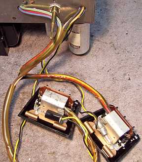
The power transformer was tested and was OK. The high voltage winding
indicated voltage balance on both sides of the center tap (with 20
volts applied to the primary through a Variac), and wattage draw was about 5
watts unloaded at full line voltage. A transformer having shorted
turns will normally draw excessive wattage unloaded (I use an real analog
wattmeter). The transformer was loose on the chassis, likely due to
shock in shipping (retained only by bent over tabs).
-
The output transformer was OK.
-
The speaker field and cone was OK, although the cone surround has been
coated with some paint-like substance.
-
All coils and the IF transformers were OK.
-
The pilot lamps were OK (type 1847) but not the correct type (should be
#44).
-
7 resistors were out of tolerance by more than 20% and would have to be
replaced.
-
One chassis bolt was missing.
-
The tubes were all
good. The 5Y3GT had been replaced with a 5Y3G. The remaining tubes
were the correct types.
-
Lots of rubber covered wiring had deteriorated and insulation was falling
off, and especially wiring for the tone switch assemblies.
-
The dial cord was slipping. It appeared to have been replaced
previously, since there were 5 turns around the tuning shaft (SAMs says 1.5
turns). However, the cord was the type with eyelets on each end, like
an original. So it is hard to tell exactly what was going
on.
-
There was some play between the dial cord pulley and the sleeve clamped to
the tuning capacitor shaft. This made tuning very difficult.
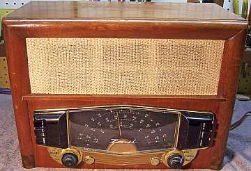
Cabinet Repair
Before starting the detailed chassis component survey or any repairs, I first
had to make sure I could reassemble the cabinet and that the radio would be
presentable afterwards. Otherwise it would make no sense to restore the
chassis. The cabinet was basically in several pieces:
- The bottom, front, and one side panel (3 pieces, loose due to glue failure
but not totally
separated)
- The top
- The opposite side and the top rear cabinet brace and back cover attachment
point still attached.
- The speaker baffle board.
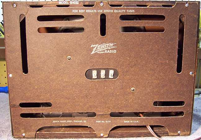
- The back cover (the taped repair was removed, and the pieces secured using
pieces of file folder cardboard, not visible from the back).
First, repairs were made to each subassembly using Titebond II carpenter's
wood glue and
suitable clamps. First the bottom, one side and front were re-glued and
clamped. The remaining parts all interlocked, so they would have to be
glued and clamped all at once. The reassembly process was first planned by
dry fitting the pieces together and determining the clamping strategy.
Once all the clamps and pieces of cardboard and waxed paper used to protect the finish were arranged,
glue was applied, clamps applied, and the glue allowed to dry overnight.
The result was quite good, but there was some damage visible is one closely
examines the radio. The result
is shown below:
Repairs
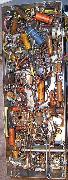
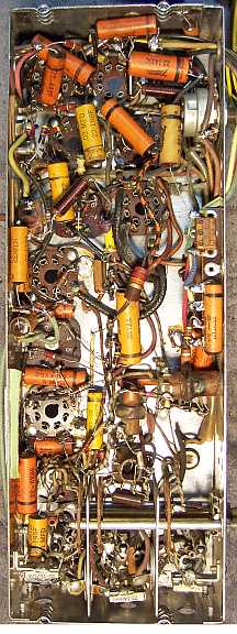
Before starting repairs I made BEFORE photos of the chassis top and bottom. I use these photos to ensure that replacement parts and
wiring are placed as close as possible to their original positions. Some
radios are subject to problems (such as oscillation or feedback) if wiring is re-routed or
lead dress is not the same as the original. Plus, I prefer to keep
the under chassis appearance as original as possible.
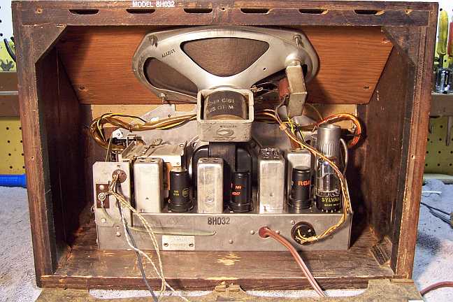
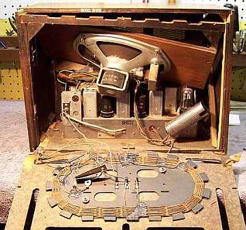
All tubes were removed. The dial assembly was removed. The chassis was
dusty, but had no rust. It was first cleaned off with an air compressor. The top and sides of the chassis
were then cleaned with small bottle
brushes and a toothbrush.
The FM antenna lead and 6S8GT shielded grid cap lead were replaced. Several other rubber covered wires with
deteriorating insulation were replaced. I used both solid and stranded
cloth covered wires (8 colors) for all replacement wiring. I use the
non-rated (smaller diameter) 20 gauge solid and stranded wire available from Radio
Daze. The AC line cord was replaced with a modern vinyl replacement.
|
Most of the
leads to the tone switches were replaced (2 of the wires were still usable). First the leads were unsoldered
from the switch assemblies. The lead colors and lengths (projections from
the clear plastic sleeving) were measured and documented. Next, the
plastic sleeving was removed by first heating with a heat gun. Next, each
wire was removed noting its color, attachment point, routing (through which hole
in the rear chassis) and total length. I did not have a suitable
replacement color for the gray wire used, so I used black, which was otherwise
not used. The above procedure was reversed in order to reassemble the
wiring to the switches. Before assembly, the switch contacts were
cleaned in my old Heathkit ultrasonic cleaner using dilute ammonia, followed by
soap, water, and a toothbrush. Only the contact portion of the switch
levers were cleaned in the ultrasonic cleaner, in order to avoid possible damage
to the lettering. |
 |
The dial cord was tightened by adding another turn on the tuning shaft.
The play in the dial pulley was eliminated by peening over the soft metal of the
collar projecting through the pulley.
Capacitors
The original power supply filter capacitor C19/C20/C21 had already been
replaced by a Sprague TVL 3787 twist-lock capacitor with a date code 7130L (30th week, 1971). I
normally would replace or restuff any filter capacitors. However, in this
case I decided to at least test it first, since Sprague capacitors are very high
quality units. First I reformed one section. It only took about 5
seconds to reform to 450 volts using my current-limited capacitor reformer, set
at 6ma. And it measured 40mfd using my HP973 DVM. I next tested it
using my Sprague TO4 capacitor tester. The leakage current was less than
100 micro amps (more like 50 micro amps - difficult to read), capacitance was
45-50mfd, and power factor 9%. So I decided to leave it in place pending
the completion of the restoration and testing. To remove this capacitor
for re-stuffing would have required removal of several small parts for
access. And it was not obvious if I could find capacitors small enough to
fit inside the can for re-stuffing. It would have require two 47mfd at 450
volts and a 47mfd at 25 volts.
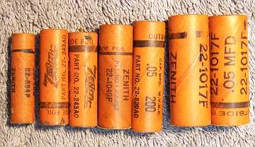
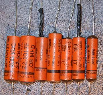
All the original Zenith paper capacitors were rebuilt in their original cases
using modern 630 volt film capacitors in order to restore or maintain the original
under-chassis appearance. In cases where an original Zenith capacitor
had been replaced during servicing, I found a suitable original dud in my parts bin and restuffed that
capacitor. I collect branded capacitors (Zenith, Philco, and others) just
for this purpose. I have been able to purchase Zenith and other branded
duds from collectors on Antique
Radio Forums and on eBay who do not restuff capacitors. 24 capacitors needed rebuilding.
In most cases I found a dud with the part number listed in SAMS. In one
case, I did not have the exact part, so I substituted a capacitor with a similar
Zenith part number having the same capacity and voltage rating. My re-stuffing process is as follows:
- The original capacitor is removed from the radio, and the required lead
length and any spaghetti sleeving use and its length noted. I also
document which capacitor lead (outside foil) goes to which terminal.
- The low melting point wax from each end is melted and removed using an old
25 watt soldering iron.
- The original wire leads are removed, as well as any remaining wax.
The leads are normally attached to the foil roll using a low melting point
metal or solder. The heat of the soldering iron used to remove the wax
will normally release the leads also.
- While the wax is still molten, a small screwdriver is used to push out the
original paper-foil roll. In some cases, the contents comes out when the leads
are pulled out.
- The original cases are then cleaned out, and any wax and dirt on the
outside removed by gently heating the body over a small alcohol lamp and
wiping with a paper towel while still molten. At this point, the cases
look like this (these are from another Zenith radio):
- If the required lead length is longer than that of the replacement
capacitor, a piece of bus wire is attached before re-stuffing (the splice
being hidden inside the case).
- The replacement capacitor is wrapped in a narrow strip of
paper towel in order to keep the new capacitor centered and to keep it from falling out. Here
are the finished capacitors from another Zenith before sealing the ends.
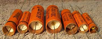
- The finished capacitor is then sealed with melted rosin (salvaged from
early RCA Superhet catacombs, and donated by or purchased from members on Antique
Radio Forums). I do NOT recoat the outside of the rebuilt
capacitors with wax (I'm not sure what was originally used - probably
beeswax).
Testing and Alignment
Once the radio chassis was reassembled and the tubes installed, power was brought up
slowly using a variac. AC power consumption was monitored using a watt meter, and a
DVM monitored the B+. The radio came alive immediately and worked on
both AM and FM bands. However, both AM and FM needed alignment. The
AM alignment was completed, and most adjustments were close except for dial
calibration. The FM100 band was working well on just the "line cord
antenna", and I am in a rural area. So I limited the FM alignment to
just the discriminator and dial calibration - I did not mess with the IF
transformers (as recommended in SAMS). The
speaker seemed to work OK - at least there was no rattle. It is hard to
judge what the effect of the white substance on the cone surround might have
been, since I do not have an original to compare with. There was hardly
any hum, and I measured only about 0.4 volts AC on the B+ line. So the
Sprague filter capacitor seems to be doing its job. But since it is 40
years old, it could of course fail at any time. But this radio will not be
a daily driver.
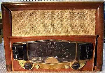
Restoration Results
Chassis Bottom Before and After Restoration